
Pressurizable sealing element

a sealing element and pressurizable technology, applied in the direction of diaphragm valves, valve details, engine components, etc., can solve the problems of not being able to meet the very specific process needs and requirements with 100 percent reliability, sealing disk damage, and sealing becoming impossibl

Active Publication Date: 2012-05-10
STADLER ACHIM
View PDF15 Cites 5 Cited by
  • Summary
  • Abstract
  • Description
  • Claims
  • Application Information

AI Technical Summary

Benefits of technology

[0005]It is an object of the present invention to provide a sealing principle which is able to constantly resist a flux pressure prevailing in a piping portion where repair works are performed, which is therefore applicable to hot-tapping processes, and which is not deformed and can therefore smoothly be removed from the flow section after completing the repair works.
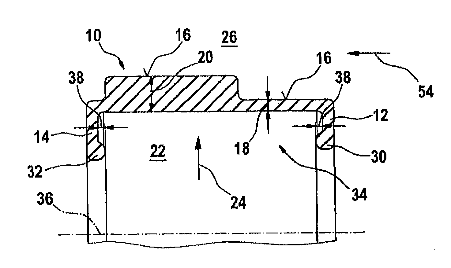
[0007]Pressurization by pressurizing media such as pressurized air or a hydraulic fluid, for example, results in the articulated or hinged deployment or erection of the pressurizable sealing element proposed by the present invention by a spring bellows or a swellable spring integrated with the sealing element and facing the pressure side, or by a portion of the lateral surface configured to have a small wall thickness. When the cavity below the sealing element is pressurized, a portion of the lateral surface which is configured to have a larger wall thickness is hingedly deployed and contacts the inner wall of the pipeline flow section to be sealed, and maintains this sealing position throughout the pressure application process performed on the sealing element. The portion which is configured to have a small wall thickness, or a bellows or a swellable spring or the like, respectively, is operable as an actuator for the hinge-like deployment of the portion of the lateral surface of the pressurizable sealing element which is configured to have a larger wall thickness, and which adapts to the inner wall of the pipe or pipeline flow section to the sealed. The pressurizable sealing element proposed by the present invention is able to reliably shut off large radial gaps between the outer periphery of the plugging head and an inner diameter of the flow section to be sealed in a range of 20 mm to 30 mm, even in case of a higher pressure level. This sealing of higher pressures is effected by at least one, preferably more than one circumferentially abutting sealing lip at a shape-retaining side of the sealing element proposed according to the present invention configured to have a larger thickness. Preferably, the at least one sealing lip is also contacted or engaged with the inner diameter of the pipeline to be sealed by a pressure applied in the media flow direction, which further assists a process-reliable sealing. This enables also the sealing of extremely non-round, already deformed, or twisted pipes.
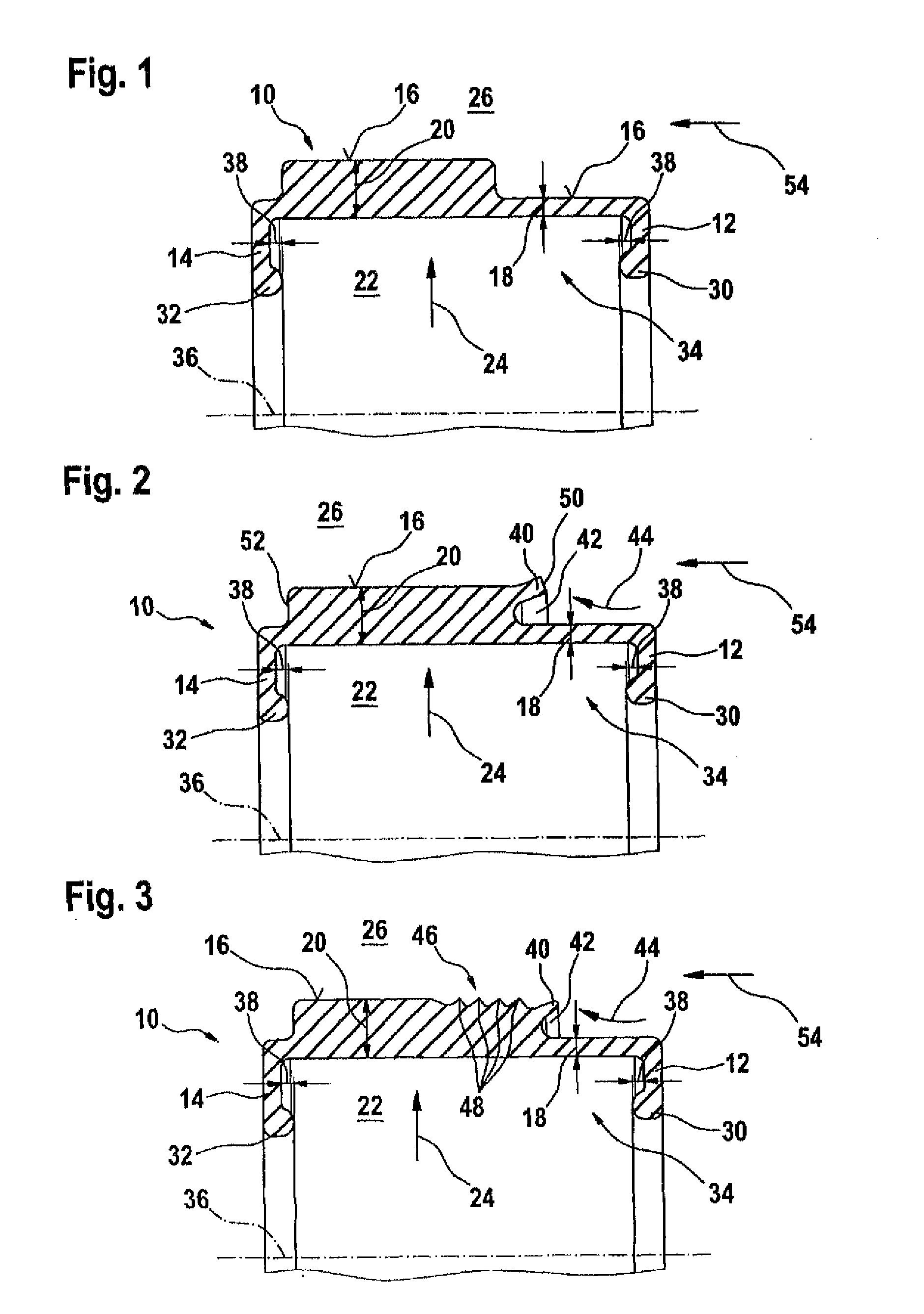
[0009]In a first embodiment, the pressurizable sealing element proposed according to the present invention may have a U-shape and bead-like thickenings at its inner surface for fixing the pressurizable sealing element in grooves formed in the end face regions of the plugging head, for example. In the first embodiment of the sealing element proposed according to the present invention, the lateral surface may be formed with a portion of reduced wall thickness which gradually changes to a portion of larger wall thickness; however, the thicker-walled portion of another, second embodiment of the pressurizable sealing element proposed according to the present invention may have a sealing lip formed at its outside. This sealing lip is located at a radial outer side, spaced apart from the outer lateral surface of the pressurizable sealing element, and is expanded by the flow-directional pressure, which further improves the tight adaptation of the sealing lip to the entire inner wall of the pipe to be sealed. When the sealing element is pressurized, it abuts to the inner wall of the flow section to be sealed along an axial sealing length.
[0014]The attachment of the pressurizable sealing element proposed according to the invention at the outer surface of a plugging head is typically effected by the above-described beads which are fixed by clamping rings accompanied by the formation of overlapping structures. The shape of said overlapping structures may influence or preset the deformation path of the lateral surface of the pressurizable sealing element proposed according to the invention. When a chamber which is open to a pressurizing hole and / or a venting hole is pressurized, the lateral surface of the pressurizable sealing element is deformed or deformed so that its outer wall adapts to the inner wall of the pipeline or the pressure-conducting pipe to be sealed while bridging a gap between them. The medium pressure which is to be shut-off acts in an expanding direction on the at least one sealing lip which is formed above a free space, and which is further pressed against the inner surface of the pipeline to be sealed, due to the action of the applied pressure to be shut-off, which further improves the sealing effect.

Problems solved by technology

In case of equipment which may be used for performing the hot-tapping or line-stopping method, respectively, common elastomeric sealing disks are usually used, none of them, however, being able to fulfill the very specific process needs and requirements with 100 percent reliability.
As a result thereof, the sealing disk may be damaged to an extent where sealing becomes impossible.
Meanwhile, it has been found that a very large radial gap between the plugging head (plug) and the inner pipeline wall of 20 mm or more cannot be sealed completely by using known approaches, and that process-reliability can therefore not be ensured.
Considerably deformed cylindrical pipes of oval cross section cannot be sealed process-reliably by the annular sealing disk mounted to the plugging head, since it is in fact their oval shape which leaves relatively large gaps that cannot be bridged or sealed by a circular sealing disk.
Moreover, it has been found that malleable sealing elements which have been used in known approaches are partly or completely undercut by the pressure to be shut off, and that it becomes impossible to dismount the whole sealing structure including the plugging head from the sealed flow section due to the constantly applied pressure which is to be shut off.

Method used


Image

  • Pressurizable sealing element
  • Pressurizable sealing element
  • Pressurizable sealing element

Examples


second embodiment

[0010]As a modification of this other, second embodiment of the pressurizable sealing element proposed according to the present invention, the portion of the molded seal configured to have a larger wall thickness may be provided with a plurality of cascading sealing lips which are arranged in a row, and which implement the sealing effect.

fourth embodiment

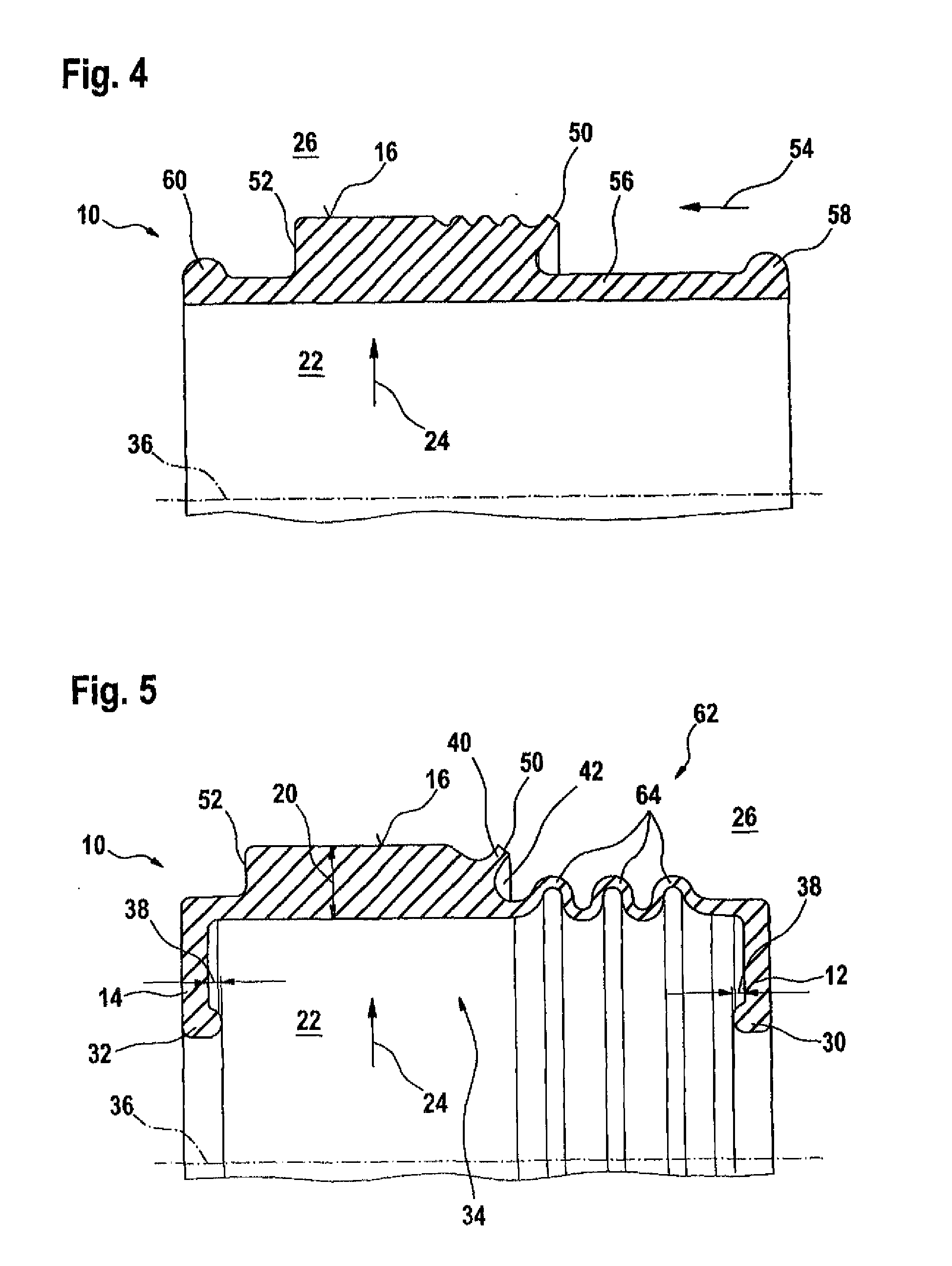
[0011]In another, fourth embodiment of the pressurizable sealing element proposed according to the invention, the bead-like thickenings of the lateral surface are configured to form the static sealing beads which extend in a radial direction. In this case, the pressurizable sealing element proposed according to the present invention is not U-shaped, but is rather of a sleeve-type which is formed without end faces, wherein the bead-like thickenings in the three preceding embodiments, which are adapted to fix the pressurizable sealing element, are located at the ends of the lateral surfaces of the sleeve-like sealing element.

[0012]In another, fifth embodiment of the idea underlying the present invention, the pressurizable sealing element is configured to have a swellable spring which is similar to a bellows. This swellable spring extends in the lateral surface of the pressurizable sealing element proposed according to the present invention in a wave-like or zigzag-like arrangement, fo...

first embodiment

[0021]FIG. 1 shows the pressurizable sealing element proposed according to the invention having lateral surface regions of differing wall thickness,

[0022]FIG. 2 shows a second embodiment of the pressurizable sealing element proposed according to the invention having a deflectable sealing lip formed in a lateral surface region,


PUM


Abstract

The invention relates to a sealing element (10) to be mounted on a plugging head (76). The plugging head (76) is introduced into an access opening in the pipeline (70) or pipe (70). The pressurizable sealing element (10) delimits at least one pressurizable cavity (22, 92) with an inner surface (78), and seals an inner wall (74) of the pipeline (70) or pipe (70) with a generated surface (16, 40, 46, 48) when a pressure pi is applied to the cavity (22, 92).

Description

TECHNICAL FIELD[0001]The present invention refers to a pressurizable sealing element made of an elastomeric material, for example for securely plugging pressurized pipes for conducting media, such as oil or gas pipes, or even water pipes.TECHNICAL BACKGROUND[0002]Special plugs which may be part of a plugging head may be used for repairing pipelines or pipes which may conduct pressurized media such as oil, gas or even water. The plugging head is part of a hot-tapping equipment for repairing pressurized pipelines, for example. Hot tapping means drilling in a pressurized state and is a method adapted for drilling a hole in a pressure-conducting body and for forming a branching or bypass or bypass line in case of pipe portions which have to be repaired or even replaced. The hot-tapping process is carried out without operational interruptions and without leakage, providing the advantage that the pipeline operation can be maintained during repair works. In addition to the hot-tapping proc...

Claims


Application Information

Patent Timeline
IPC IPC(8): F16K31/12
CPCF16K7/10F16K7/02
Inventor STADLER, ACHIMBARTH, ARMIN
Owner STADLER ACHIM
Learn More