Rotation angle calculation apparatus and rotation angle calculation method

a technology of rotation angle and calculation apparatus, which is applied in the direction of electronic commutators, motor/generator/converter stoppers, dynamo-electric converter control, etc., can solve the problems of relative long time lag corresponding and the inability to correct errors as appropriate, and achieve the effect of deteriorating the accuracy of error correction

Active Publication Date: 2012-05-10
DENSO CORP
View PDF11 Cites 7 Cited by
  • Summary
  • Abstract
  • Description
  • Claims
  • Application Information

AI Technical Summary

Benefits of technology

[0021]In accordance with the present invention, in the case where an error of a multipole resolver is to be corrected, deterioration

Problems solved by technology

If, however, the detected angle is corrected individually for each section (for each pole) like Patent Document 1, there is a relatively long time lag corresponding to one period in which the motor makes one full rotation, between the tim

Method used


Image

  • Rotation angle calculation apparatus and rotation angle calculation method
  • Rotation angle calculation apparatus and rotation angle calculation method
  • Rotation angle calculation apparatus and rotation angle calculation method

Examples


first modification

[0083]In the above-described first embodiment, rotation speed variation α is used as the transition index. Instead of rotation speed variation α, a variation per unit time of the torque of motor M1 (hereinafter referred to as “torque variation β”) may be used.

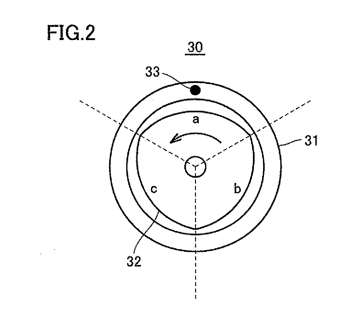
[0084]FIG. 8 is a diagram illustrating a correspondence between torque variation β and the way to correct an error, Where torque variation β is large, a variation in electric current flowing in motor M1 is also large, resulting in a large variation in leakage magnetic flux of motor M1. Since resolver 30 generates an electrical signal in accordance with the rotation angle of motor M1 based on a change in magnetic flux as described above, detected angle θ is influenced by magnetic noise such as leakage magnetic flux of motor M1. Therefore, if torque variation β is large, a variation of error Errθ is also large due to the influence of the large torque variation.

[0085]In view of the above, as shown in FIG. 5, the normal correction ...

second modification

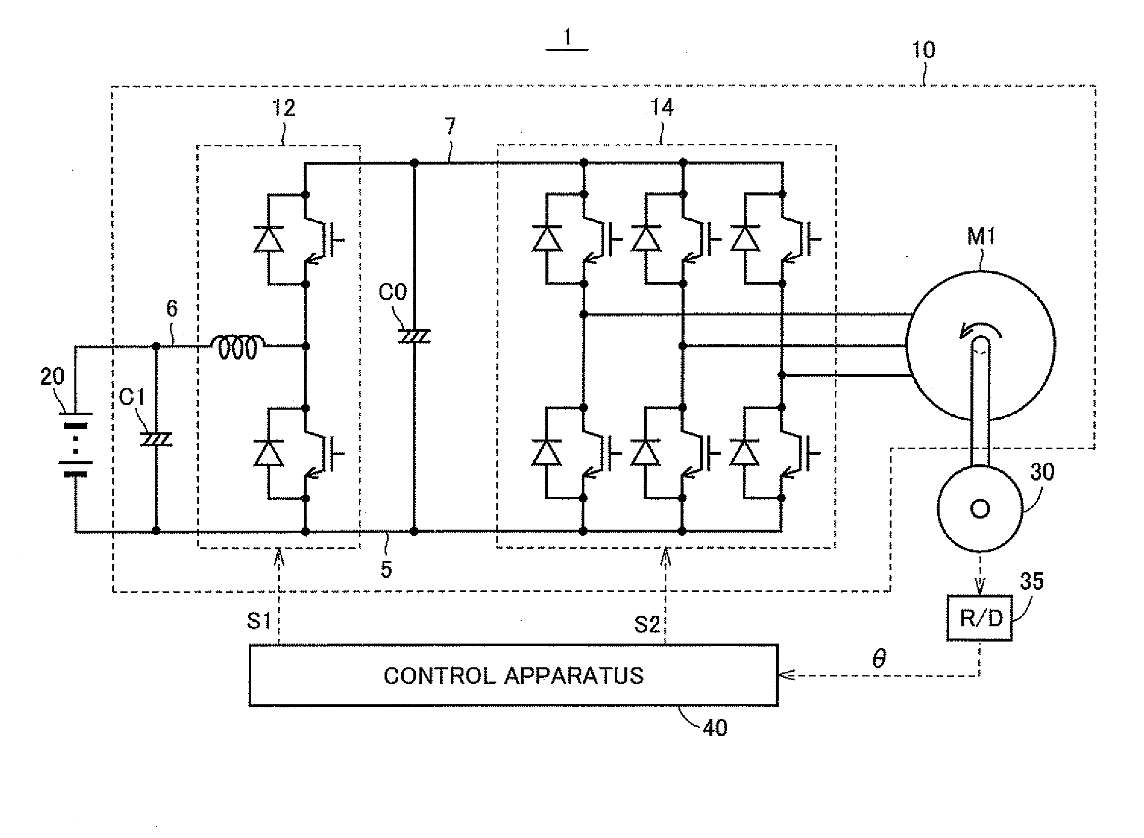
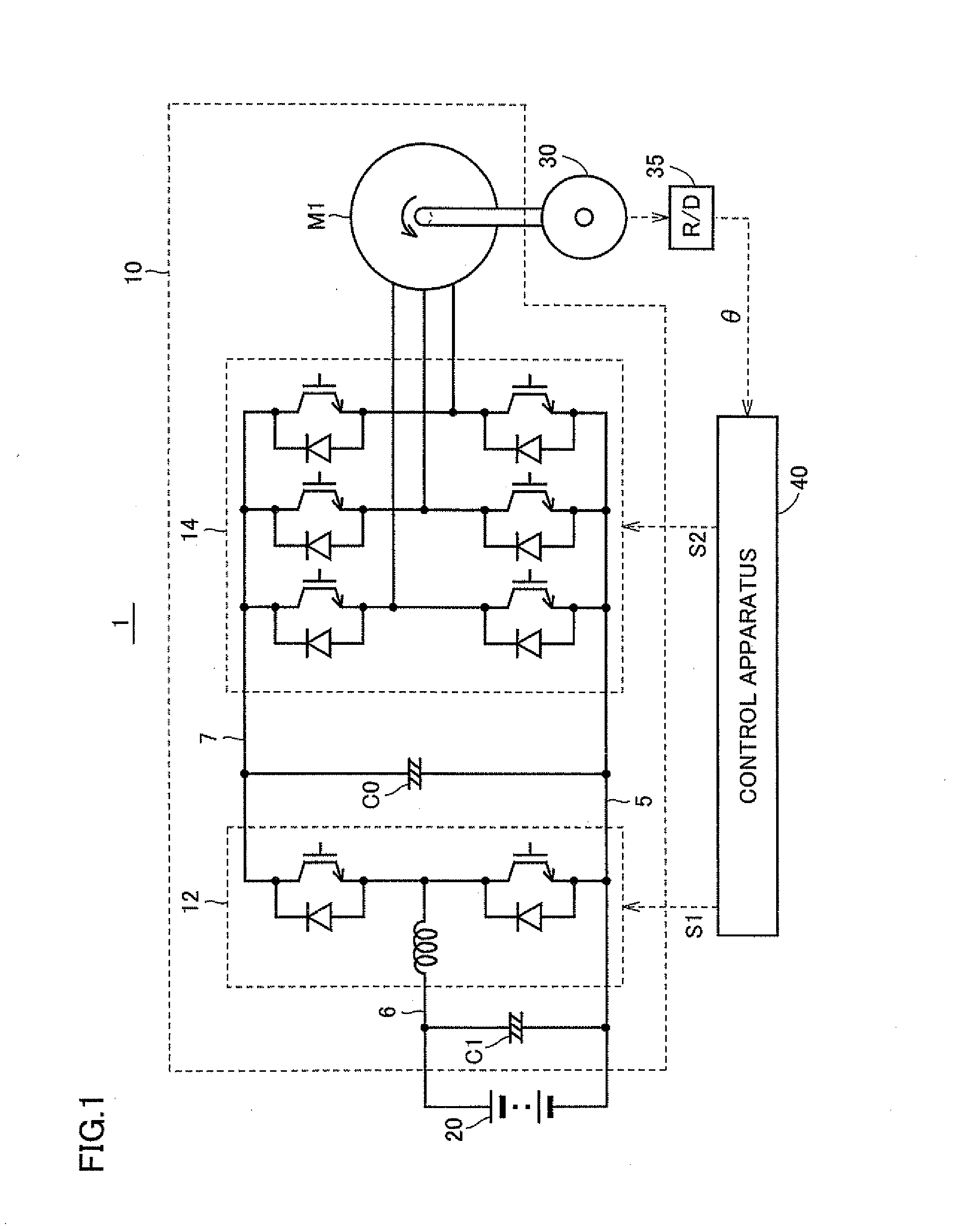
[0087]While the transition index in the above-described first embodiment is rotational speed variation α, variation per unit time of a voltage that is input from converter 12 to inverter 14 (hereinafter referred to as “voltage variation y”) may be used instead of rotation speed variation α.

[0088]FIG. 9 is a diagram illustrating a correspondence between voltage variation γ and the way to correct an error. Where voltage variation γ is large, a change in switching period of converter 12 is also large, resulting in a large change in electrical noise such as switching surge.

[0089]As described above, resolver 30 generates an electrical signal in accordance with the rotation angle of motor M1 and communicates the electrical signal with R / D circuit 35. Detected angle θ is therefore influenced by electrical noise such as switching surge.

[0090]Therefore, if voltage variation γ is large, a variation in error Errθ is also large due to the influence of the large voltage variation.

[0091]In view o...

third modification

[0093]In the above-described first embodiment, rotation speed variation α is used as the transition index. Instead of rotation speed variation α, a carrier frequency f used for controlling switching of inverter 14 may be used.

[0094]Here, carrier frequency f will be described. Control apparatus 40 controls inverter 14 by means of pulse width modulation (hereinafter also referred to as “PWM”) control. Under this PWM control, the switching devices of inverter 14 are turned on or off based on a voltage comparison between a carrier signal and a voltage command, to thereby apply a pulse width modulated voltage from inverter 14 to motor M1. Therefore, the switching period of inverter 14 depends on the frequency of the carrier signal. This frequency of the carrier signal is “carrier frequency f”. Control apparatus 40 changes carrier frequency f depending on the state of drive apparatus 10 or the like.

[0095]FIG. 10 is a diagram illustrating a correspondence between carrier frequency f and th...


PUM


Abstract

A control apparatus using a multipole resolver for calculating the rotation angle of a motor includes an acquisition unit, a learning unit, a calculation unit, and a correction unit. The acquisition unit acquires a detected angle θ detected by the multipole resolver. The learning unit learns the waveform of an error Errθ for each pole of the resolver. The calculation unit calculates a motor's rotational acceleration variation α. The correction unit compares the rotation speed variation α with a threshold value α0. Where α<α0, the correction unit performs a normal correction of calculating a corrected angle φ using an error Errθ of one mechanical period (in which the motor makes one full rotation) ago. In contrast, where α>α0, the correction unit performs a transition correction of calculating a corrected angle φ using an immediately preceding error Errθ.

Description

[0001]This is a Continuation of PCT Application No. PCT / JP2010 / 069785 filed Nov. 8, 2010. The entire contents of which are hereby incorporated by reference.BACKGROUND OF THE INVENTION[0002]1. Field of the Invention[0003]The present invention relates to a technique of calculating the rotation angle of a motor by means of a multipole resolver.[0004]2. Description of the Background Art[0005]Conventionally, a technique of detecting or calculating, by means of a resolver, the rotation angle of a motor which is mounted on a hybrid vehicle, electric vehicle or the like has been known. The resolver is attached to the rotating shaft of the motor, and generates an electrical signal (analog signal) in accordance with the rotation angle of the motor, based on a change in magnetic flux. The electrical signal generated by the resolver is converted into an angular signal (digital signal) by a resolver-to-digital conversion circuit. While the torque of the motor is controlled based on the angular s...

Claims


Application Information

Patent Timeline
IPC IPC(8): H02P6/16H02P27/06H02P27/08
CPCH02P6/18G01D5/24476G01D5/24495
Inventor NIIMI, YOSHITAKA
Owner DENSO CORP
Why Eureka
Try Eureka