Frequency synthesizer and frequency synthesizing method

Inactive Publication Date: 2012-05-10
SONY CORP
View PDF10 Cites 58 Cited by
  • Summary
  • Abstract
  • Description
  • Claims
  • Application Information

AI Technical Summary

Benefits of technology

[0005]It is an object of the present invention to provide a frequency synthesizer and a corresponding frequency synthesizing method providing improved phase noise, very fine frequency resolution, agile frequency switching and at the same time very good sweep linearity (required e.g. for some radar applications).

Problems solved by technology

The requirements of the microwave systems are getting tough, so that the known synthesizers cannot fulfil requirements such as phase noise, switching speed, fine resolution, and frequency sweep.
Recently, new hybrid architectures were developed which combines direct digital synthesizer (DDS) and phase look loops (PLL) which, however, can also not fulfil all these requirements.
However, this frequency synthesizer suffers also from a high division ratio in the feedback loop as the downconversion of the signal can only be as much as the highest frequency output of the DDS.
Commercially available DDS circuits are limited mainly to frequencies below 1 GHz.
This results in a large phase noise degradation.
For millimeter wave frequencies, this frequency synthesizer is thus not applicable because of the high phase noise of the synthesized signal.

Method used


Image

  • Frequency synthesizer and frequency synthesizing method
  • Frequency synthesizer and frequency synthesizing method
  • Frequency synthesizer and frequency synthesizing method

Examples


first embodiment

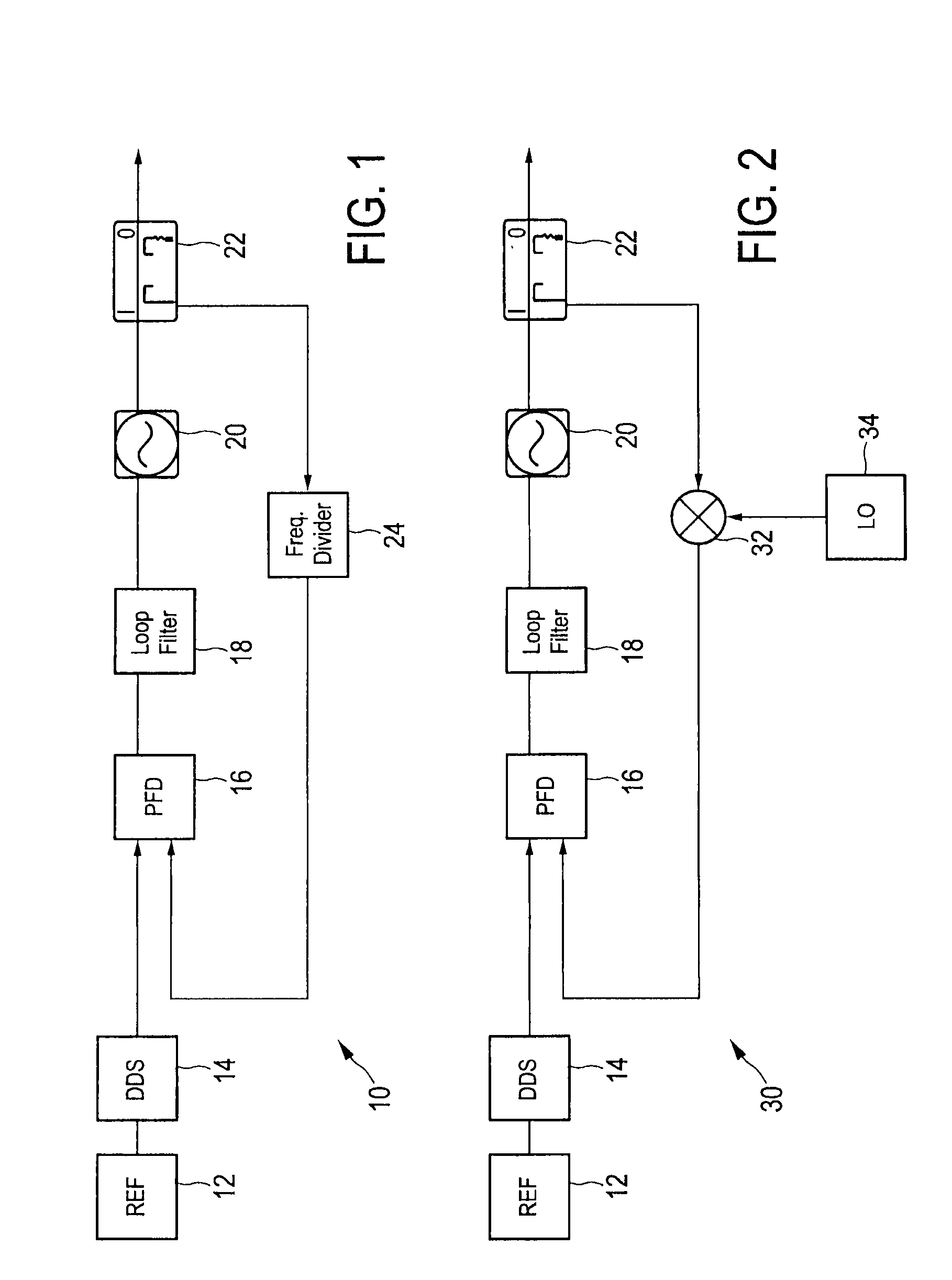
[0040]FIG. 1 shows a hybrid DDS / PLL frequency synthesizer 10 as, for instance, described in Stelzer, A.; Kolmhofer, E.; Scheiblhofer, S., “Fast 77 GHz chirps with direct digital synthesis and phase locked loop”, Microwave Conference Proceedings, 2005, APMC 2005, Asia-Pacific Conference Proceedings, vol. 3, 4-7 Dec. 2005. This frequency synthesizer comprises a DDS (direct digital synthesizer) 14, which receives a reference signal from a reference signal source 12 and which it turn is used as a reference input for a phase detector 16. The phase detector 16 (also called phase frequency detector; PFD detects frequency and phase differences between the reference signal from the DDS 14 and a feedback signal from a feedback loop. A loop filter 18 is coupled to the output of the phase detector 16 for filtering the control signal output from the phase detector 16. A controlled oscillator 20, e.g. a voltage controlled oscillator (VCO), is coupled to the output of the loop filter 18 and genera...

second embodiment

[0043]FIG. 2 shows a hybrid DDS / PLL frequency synthesizer 30 having an offset loop as, for instance, described in Wagner, C.; Feger, R.; Haderer, A.; Fischer, A.; Stelzer, A.; Jager, H., “A 77-GHz FMCW radar using a digital phase-locked synthesizer”, Microwave Symposium Digest, 2008, IEEE MTT-S International, vol. 57, no. 5, pp. 351-354, 15-20 Jun. 2008 and Wagner, C.; Stelzer, A.; Jager, H., “Estimation of FMCW radar system performance using measurement data of a 77-GHz transmitter”, Microwave Conference, APMC 2006, Asia-Pacific, pp. 1701-1704, 12-15 Dec. 2006. This embodiment of the frequency synthesizer 30 is to a large extent identical to the embodiment of the frequency synthesizer 10 shown in FIG. 1. Instead of the frequency divider 24, however, a mixer 32 is used in the feedback loop, said mixer 32 being provided with a mixing frequency from a local oscillator 34, to down-convert the output frequency of the frequency output signal provided by the output unit 22 to the phase de...

third embodiment

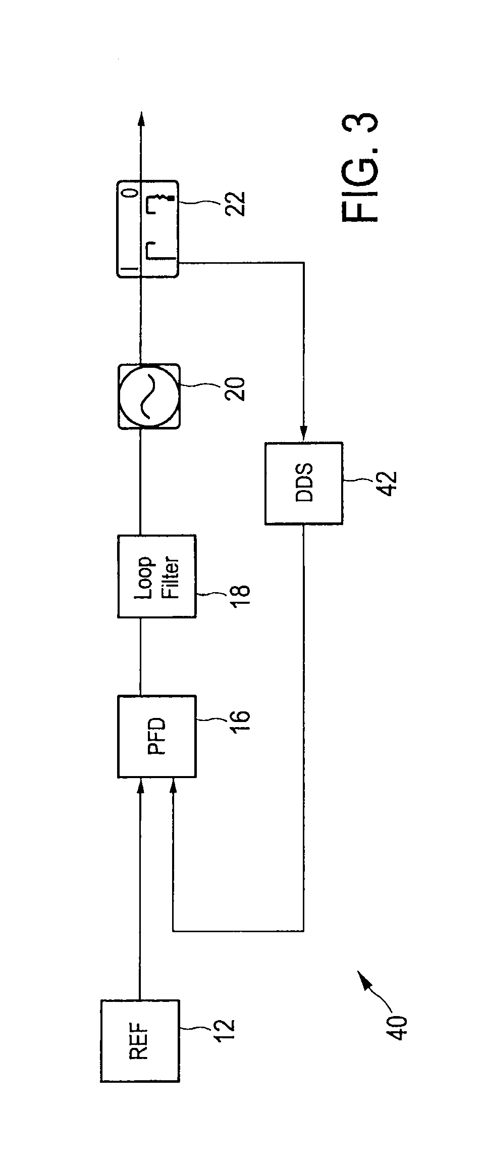
[0044]FIG. 3 shows a hybrid DDS / PLL frequency synthesizer 40 having a fractional loop as, for instance, described in Stelzer, A.; Kolmhofer, E.; Scheiblhofer, S., “Fast 77 GHz chirps with direct digital synthesis and phase locked loop”, Microwave Conference Proceedings, 2005, APMC 2005, Asia-Pacific Conference Proceedings, vol. 3, 4-7 Dec. 2005. Compared to the embodiment of the frequency synthesizer 10, 30 shown in FIG. 1 the DDS 42 is located in the feedback loop rather than between the reference signal source 12 and the phase detector 16. There is no need for an additional clock signal for the DDS 42. In addition, as reference for the phase detector 16 the reference signal provided from the reference signal source 12, which has a very good phase noise, is used. However, this embodiment has a non-linearity problem during a continuous frequency sweep. Further, also the oscillator frequency of the oscillator 20 must be divided at least to the maximum DDS input frequency, which contr...


PUM


Abstract

The present invention relates to a frequency synthesizer comprising a main unit and a side unit. The main unit comprises a main phase detector to obtain a main control signal, a main oscillator that generates a main synthesized frequency output signal representing the frequency synthesizer output signal based on said main control signal, and a mixer that mixes said main synthesized frequency output signal with a side synthesized frequency output signal to obtain said mixer output signal. The side unit generates said side synthesized frequency output signal and comprises a frequency signal generation unit that provides a linear frequency sweep signal or a fixed-frequency control signal at a fine frequency resolution from said fixed-frequency side reference signal, and a side oscillator that generates said side synthesized frequency output signal based on said frequency sweep signal or said fixed-frequency control signal.

Description

CROSS-REFERENCE TO RELATED APPLICATIONS[0001]The present application claims priority of European patent application 10190562.8 filed on Nov. 9, 2010.FIELD OF THE INVENTION[0002]The present invention relates to a frequency synthesizer and a corresponding frequency synthesizing method.BACKGROUND OF THE INVENTION[0003]Frequency synthesizers are key building blocks of any microwave system. They are found in many modern devices, including radio receivers, mobile telephones, satellite receivers, GPS systems, radars, etc. . . . . There are three main synthesizer architectures, in particular direct analog, direct digital and indirect (Phase Lock Loop) synthesizers. The requirements of the microwave systems are getting tough, so that the known synthesizers cannot fulfil requirements such as phase noise, switching speed, fine resolution, and frequency sweep. Recently, new hybrid architectures were developed which combines direct digital synthesizer (DDS) and phase look loops (PLL) which, howe...

Claims


Application Information

Patent Timeline
IPC IPC(8): H03L7/087
CPCH03L7/089H03L7/093H03L2207/12H03L7/23H03L7/099
Inventor DAYI, FURKAN
Owner SONY CORP
Why Eureka
Try Eureka