
Integrated Microfluidic Device and Methods

a microfluidic device and integrated technology, applied in the field of microfluidics, can solve the problems of many existing microfluidic devices being restricted, limiting the practicality with which the system can be utilized in various chemical or biological assays, and being difficult to adapt or customize for other applications

Active Publication Date: 2012-05-10
RHEONIX
View PDF4 Cites 48 Cited by
  • Summary
  • Abstract
  • Description
  • Claims
  • Application Information

AI Technical Summary

Problems solved by technology

However, existing microfluidic systems lack adequate mechanisms for allowing controlled manipulation of multiple fluids except via prescribed flow patterns, hence limiting the practicality with which the systems can be utilized in various chemical or biological assays.
This is because real-world assays often require repetitive manipulation of different reagents for various analytical purposes.
Moreover, many existing microfluidic devices are restricted for one specific use and cannot be easily adapted or customized for other applications without being completely redesigned.
These devices lack modularity, and therefore cannot share common device components that allow one design to perform multiple functions.
This lack of flexibility leads to increased production costs as each use requires the production of a different system.
Furthermore, many existing microfluidic systems lack any means for straightforward end-point assays that are able to easily detect interactions or existence of analytes resulting from the assays.

Method used


Image

  • Integrated Microfluidic Device and Methods
  • Integrated Microfluidic Device and Methods
  • Integrated Microfluidic Device and Methods

Examples


example 1

6.1 Example 1

Microfluidic Device Embodiment with Three Functional Areas

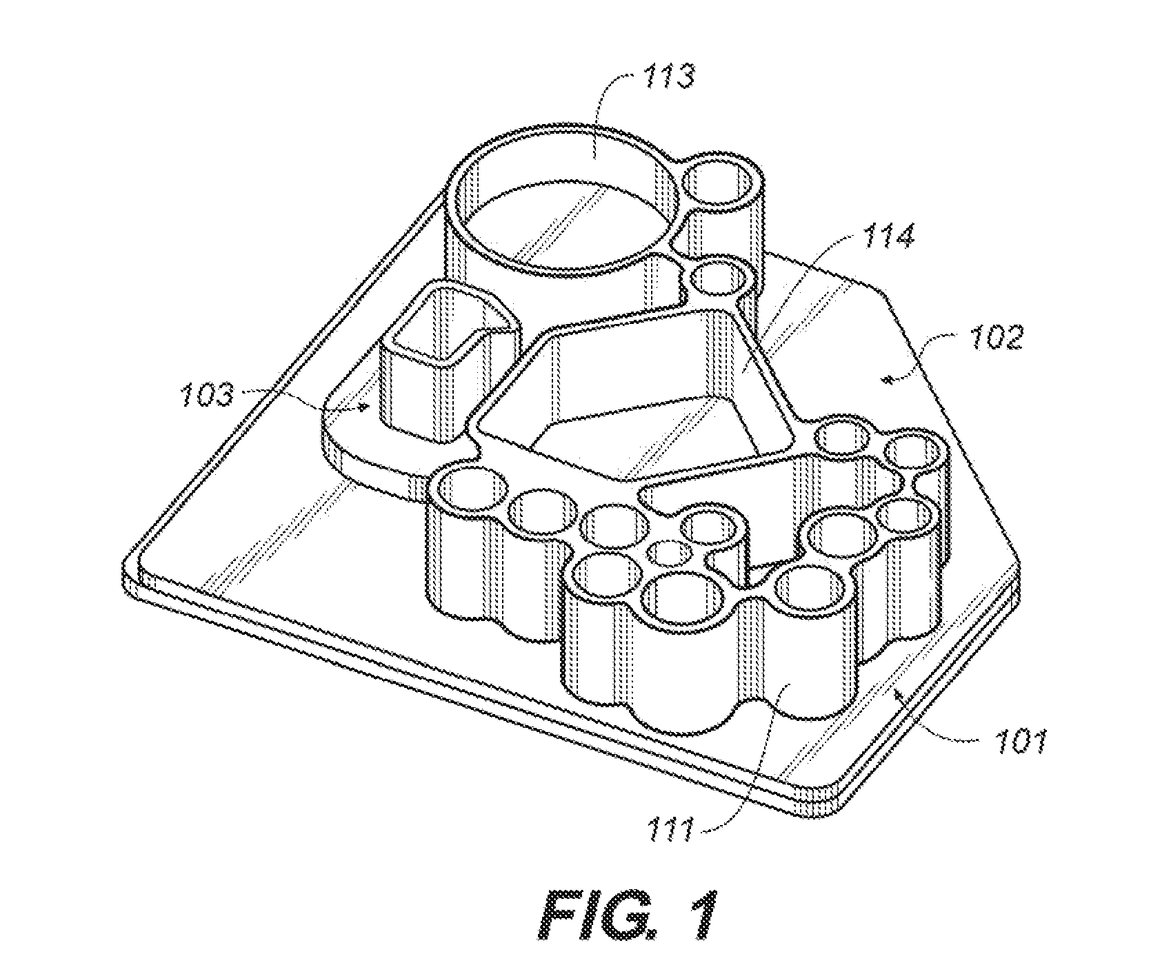
[0330]This example describes an embodiment of the microfluidic device (“chip”) that has three functional areas, a sample preparation area, a nucleic acid amplification area and a nucleic acid analysis area is an area for carrying out amplification product assays (FIGS. 1-7) and an exemplary method for using the device.

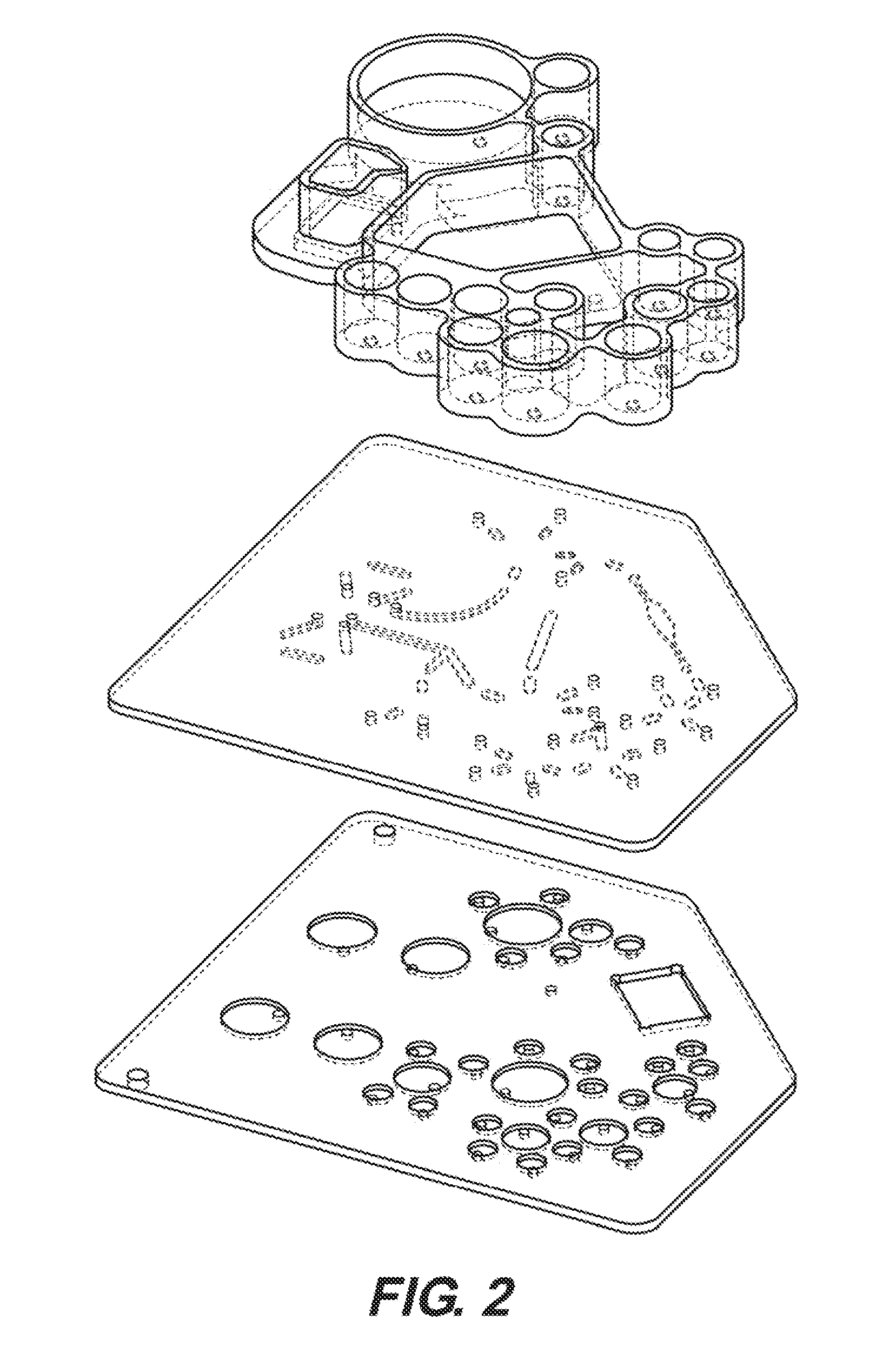
[0331]FIG. 2 is an isometric exploded view of the embodiment of the microfluidic device in FIG. 1, showing the valve map.

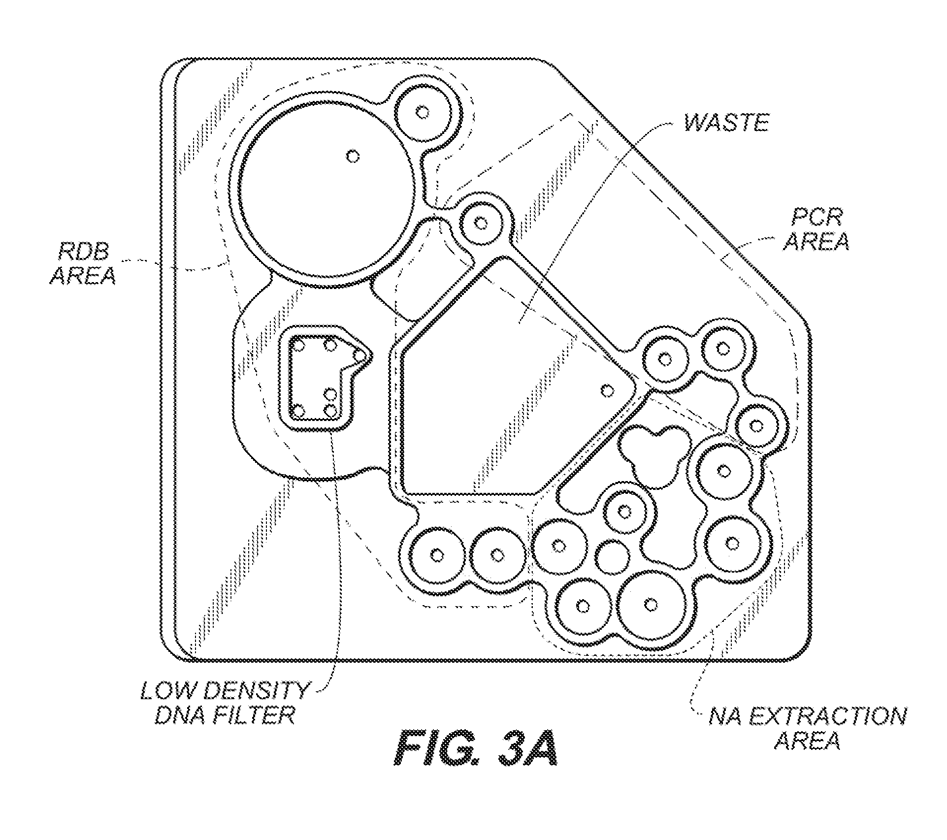
[0332]FIG. 3A is a top view of the embodiment of the microfluidic device in FIG. 1, showing the sample preparation area (“nucleic acid (NA) extraction area”), the nucleic acid amplification area (in this embodiment, a “PCR area”) and the nucleic acid analysis area (“RDB area”). Also shown is the layout of valves, microfluidic channels, through-holes, and a low density DNA filter on the device. In this embodiment, a reverse dot blot (RDB) end-point detection assay can be performed ...

example 2

6.2 Example 2

Microfluidic Device Embodiment with Two Functional Areas

[0338]This example describes another embodiment of the microfluidic device (“chip”) that has two functional areas (FIGS. 8-11) and a method for using it.

[0339]FIG. 8 shows another embodiment of the microfluidic device with two functional areas, the sample preparation area and the nucleic acid amplification area. As indicated by arrows, the sample preparation area comprises reservoirs for sample input and preparation, sample purification and nucleic acid extraction. The nucleic acid amplification area comprises a nucleic acid amplification reactor (“amplification chamber”). This embodiment of the device also comprises a nucleic acid amplification products extraction area (“amplified products extraction area”), which is an area in which amplicons are extracted from the microfluidic device after nucleic acid amplification is complete. This particular embodiment of the device has dimensions of 50 mm×38 mm.

[0340]FIG. 9 ...

example 3

6.3 Example 3

Microfluidic Device Embodiment with Two Functional Areas

[0347]This example describes another embodiment of the microfluidic device (“chip”) that has two functional areas, a sample preparation area and a nucleic acid amplification area, but does not have an on-chip nucleic acid analysis area (FIGS. 12-16).

[0348]The device has body dimensions of 50 mm×38 mm and comprises three sandwiched layers that are bonded by a weak solvent bonding method of U.S. Patent Application 2006 / 0078470A1. The device further comprises a plurality of reservoirs disposed on a top surface of the device and in fluid connection with various valves and network of fluid channels. The device also comprises a nucleic acid amplification reactor that forms part of the functional fluidic network.

[0349]FIG. 13 shows the layout of the embodiment of the microfluidic device shown in FIG. 12, with three groups of bi-directional pumps depicted: for sample preparation, for PCR reagent preparation and for loading...


PUM

PropertyMeasurementUnit
thicknessaaaaaaaaaa
thicknessaaaaaaaaaa
thicknessaaaaaaaaaa

Abstract

A microfluidic device for analyzing a sample of interest is provided. The microfluidic device can comprise a microfluidic device body, wherein the microfluidic device body comprises a sample preparation area, a nucleic acid amplification area, a nucleic acid analysis area, and a network of fluid channels. Each of the sample preparation area, the nucleic acid amplification area and the nucleic acid analysis area are fluidly interconnected to at least one of the other two areas by at least one of the fluid channels. Using the microfluidic device, sample preparation can be combined with amplification of a biologically active molecule, and a suitable biological sample can be provided for analysis and / or detection of a molecule of interest. The small-scale apparatus and methods provided are easier, faster, less expensive, and equally efficacious compared to larger scale equipment for the preparation and analysis of a biological sample.

Description

CROSS-REFERENCE TO RELATED APPLICATIONS[0001]This application claims priority to and the benefit of co-pending U.S. provisional patent application Ser. No. 60 / 979,515, filed Oct. 12, 2007, which is incorporated herein by reference in its entirety.STATEMENT REGARDING FEDERALLY SPONSORED RESEARCH OR DEVELOPMENT[0002]Not applicableREFERENCE TO APPENDIX[0003]Not applicable.1. TECHNICAL FIELD[0004]The present invention relates to the field of microfluidics and the application of microfluidics in the fields of biochemistry and molecular biology. The invention further relates to integrated microfluidic platform apparatuses and associated methods. The invention also relates to microfluidic devices for preparing, amplifying and detecting biological molecules of interest, such as nucleic acids. The invention also relates to methods for preparing, amplifying and detecting biological molecules of interest, such as nucleic acids using microfluidic devices.2. BACKGROUND OF THE INVENTION[0005]Mole...

Claims


Application Information

Patent Timeline
Patent Type & Authority Applications(United States)
IPC IPC(8): C12Q1/68C40B30/04C12M1/40
CPCB01F5/0683B01L2400/084B01F11/0074B01F13/0059B01L3/50273B01L7/52B01L2200/027B01L2200/0621B01L2200/10B01L2300/0816B01L2300/1816B01L2300/1822B01L2300/1827B01L2300/1844B01L2300/185B01L2400/0487B01L2400/0638B01F5/0688B01F25/451B01F25/4521B01F31/651B01F33/30
Inventor ZHOU, PENGYOUNG, LINCOLN C.ROSWECH, TODDSPIZZ, GWENDOLYNCHEN, ZONGYUANTHOMAS, BENJAMIN W.LEE, TRAVIS
Owner RHEONIX
Learn More