Microseismic source location estimation method with high resolution using green's functions

a microseismic source and function technology, applied in seismology for waterlogging, using reradiation, instruments, etc., can solve the problems of high signal/noise ratio, high signal/noise ratio, and inability to direct measurement of fluid flow in reservoirs, if at all possible, so as to improve image accuracy and confirm the reliability of green functions

Inactive Publication Date: 2012-05-10
SAUDI ARABIAN OIL CO
View PDF2 Cites 13 Cited by
  • Summary
  • Abstract
  • Description
  • Claims
  • Application Information

AI Technical Summary

Benefits of technology

[0026]The “natural” Green's function is constructed, e.g., by correlating the drill bar vibration corresponding to the pilot signal for the drill bit with the seismic waves generated by the drill bit while drilling in the region of interest. The Green's function(s) are also derived by summing correlated traces between master traces and the remaining traces in shot gathers. In this method, all of the natural arrivals in the data are used. When additional measurements become available, the data can be used to further refine and / or confirm the reliability of the Green's functions that have been applied. The additional measurement can also be used as a cross-check for the method of the invention. The additional measurements can also be used in combination with the method of the invention to improve the accuracy of the images generated.

Problems solved by technology

Direct measurement of fluid flow in the reservoirs, if at all possible, is a complex and expensive task.
A problem encountered in the field is that the required precision of the microseismic source location is beyond the seismic resolution of a typical passive seismic array located on the surface.
The narrow aperture of the surface receivers, high signal / noise ratios, and the relatively long wavelengths of the source prevent a precise seismic estimate of where the rock is being fractured.
The known methods of the prior art in some instances produce results lacking in the desired level of accuracy in mapping the microseismic event source locations due to the assumptions made in processing the data utilized and / or the methods require complex, and therefore expensive, arrays of equipment to collect the data required to practice the method.
One particular limitation is the requirement of developing a velocity model.

Method used


Image

  • Microseismic source location estimation method with high resolution using green's functions
  • Microseismic source location estimation method with high resolution using green's functions
  • Microseismic source location estimation method with high resolution using green's functions

Examples


Embodiment Construction

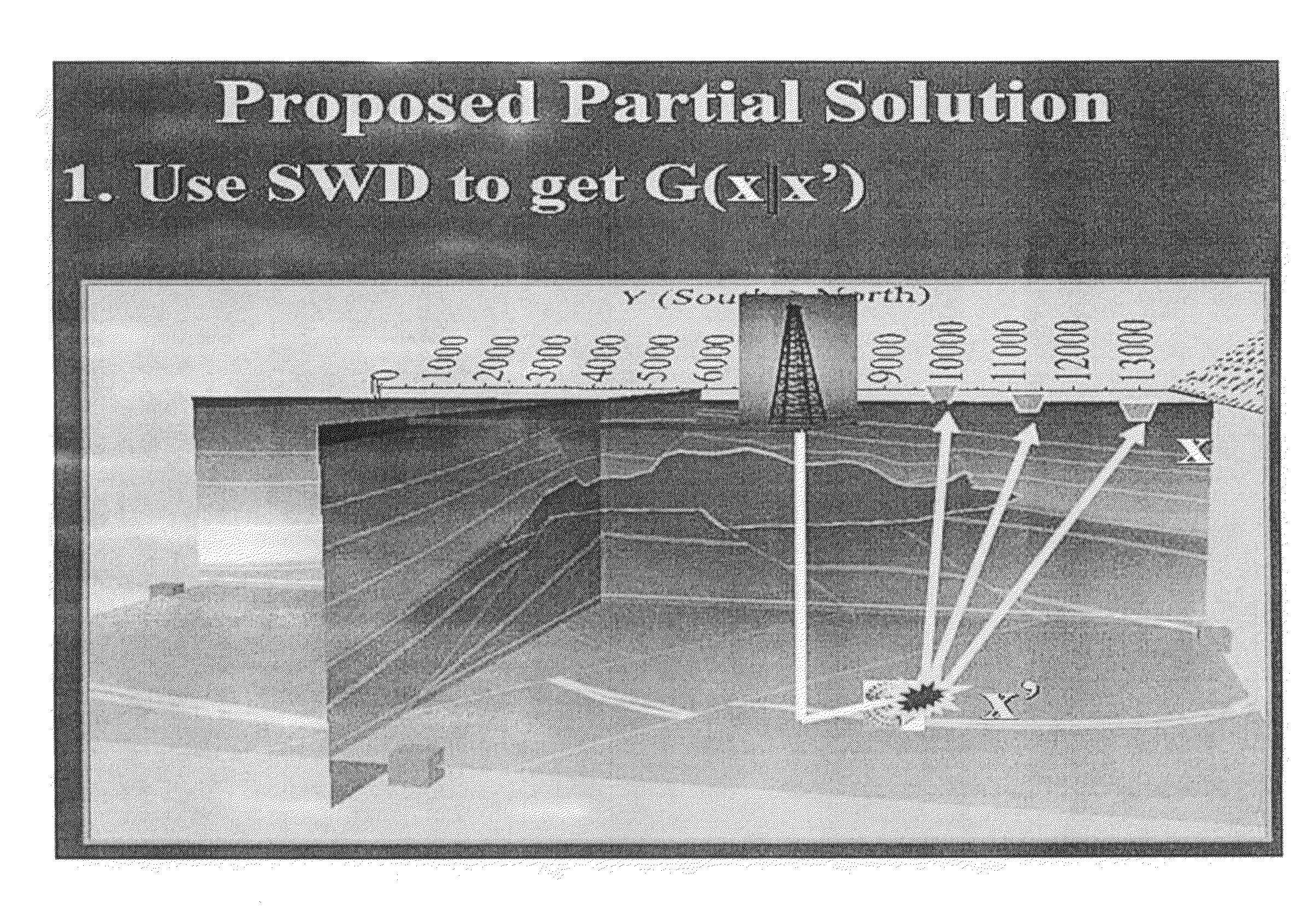
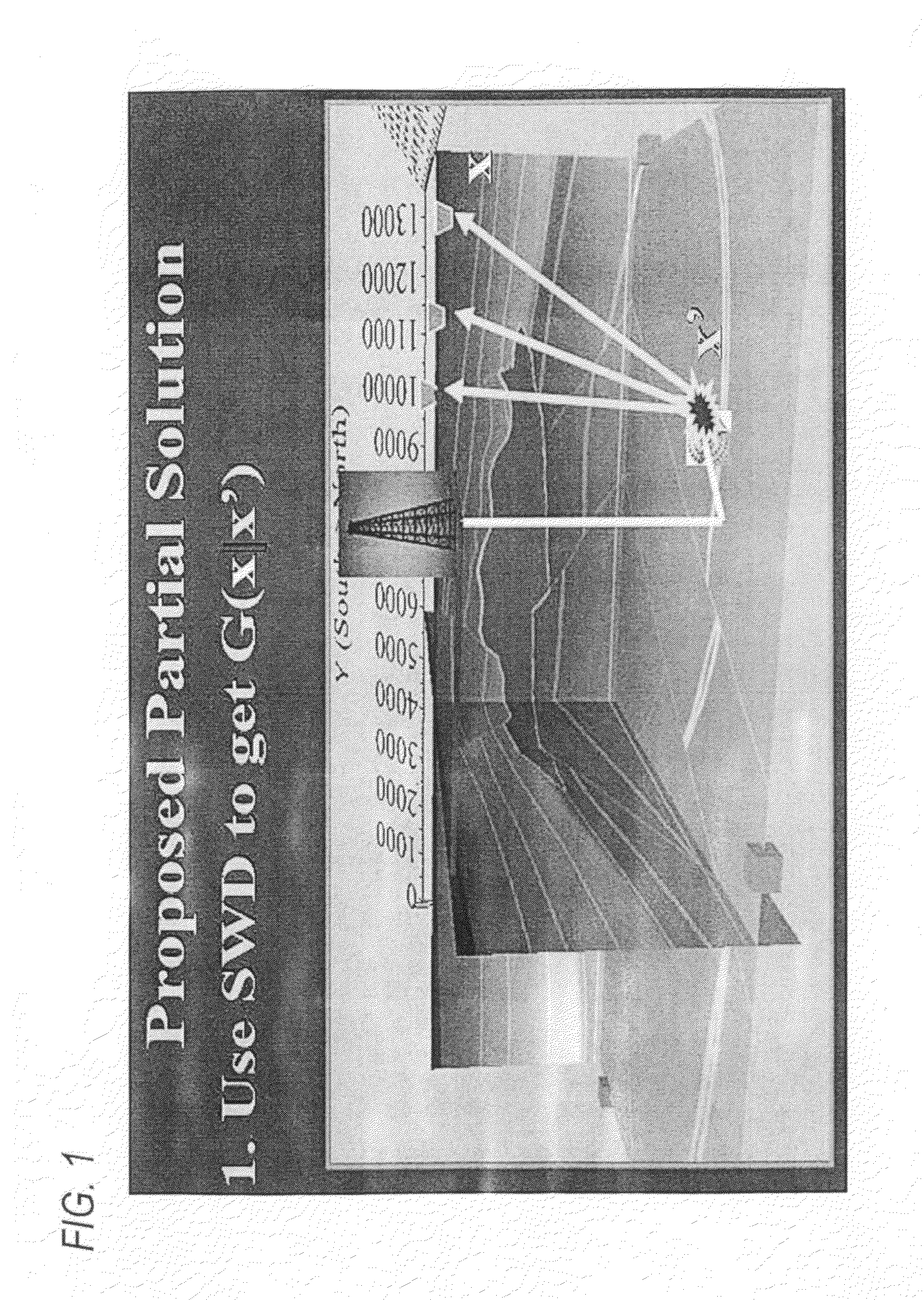
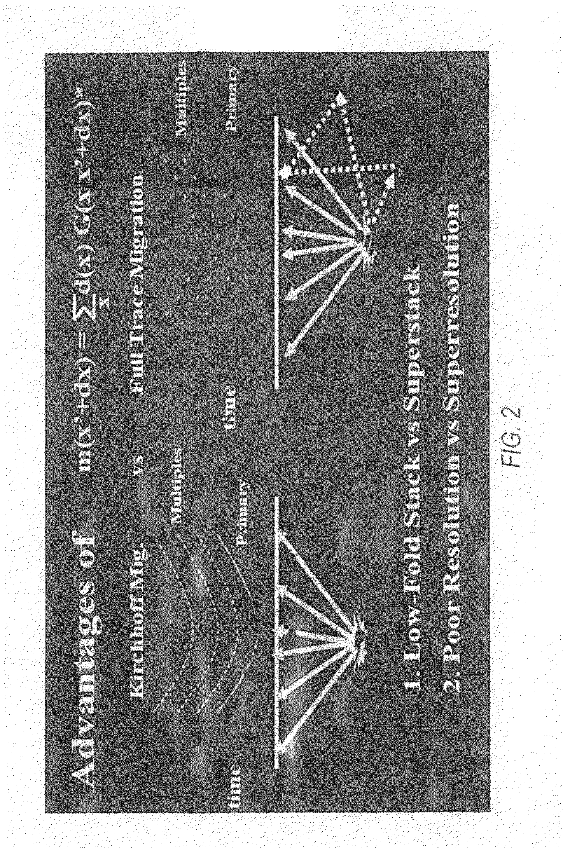
[0040]In accordance with this invention, Green's function G(x,z,t|x′,z′,0) is estimated from various data sources, including RVSP, VSP, SWD or surface data, and used to provide images of the estimated locations of hydro-frac sources with a high degree of resolution. These Green's functions can be used as the migration kernels to estimate hydro-frac source locations with greater accuracy than the diffraction limit, because all of the natural arrivals in the data are utilized.

[0041]Green's function can be estimated from surface seismic data using two different methods. The first method is to use the drill bit as a seismic source as is known in the seismic-while-drilling (SWD) methods. The seismic data are recorded on the surface and correlated with the recorded pilot signal to give the impulse-like Green's function. Evaluation of the Green's function far from the drill bit is achieved by employing a wavefield continuation method using a local velocity model.

[0042]2. The second method ...


PUM


Abstract

The sources of microseismic hydraulic fracture events (“hydro-fracs”) are located for image mapping by the calculation of Green's functions G(x,z,t|x′,z′,0) which is estimated using, e.g., RVSP, VSP, SWD and/or surface data, with the Green's functions used as migration kernels with greater accuracy than the prior art techniques, e.g. the diffraction limit, because all of the natural arrivals in the data are utilized.

Description

FIELD OF THE INVENTION[0001]The invention relates to the monitoring and estimation, with a high degree of resolution, of the location of subsurface microseismic sources associated with fluid movement in hydrocarbon-containing reservoir rock.BACKGROUND OF THE INVENTION[0002]The accurate monitoring of fluid movement in hydrocarbon reservoirs is essential for increasing the recovery from the reservoir rock reserves. Direct measurement of fluid flow in the reservoirs, if at all possible, is a complex and expensive task. As a result, indirect methods have been investigated. One useful approach is to measure source locations of seismic events, which are often triggered by rock fractures resulting from fluid movement. These microseismic hydraulic fracture events are also referred to as “hydro-fracs”. An important step in locating the seismic sources are the calculation of Green's functions, which can be used to map the recorded seismic energy to where it was generated to thereby identifyin...

Claims


Application Information

Patent Timeline
Patent Type & Authority Applications(United States)
IPC IPC(8): G01V1/40G06F19/00
CPCG01V1/288G01V1/375G01V2210/65G01V2210/1234G01V1/42
Inventor FEI, TONG W.LUC, YIALFARAJ, MOHAMMED N.SOHUSTER, GERARD T.
Owner SAUDI ARABIAN OIL CO
Why Eureka
Try Eureka