
Flow Chart Programming Platform for Testers and Simulators

a programming platform and simulator technology, applied in the field of flow chart programming platform for testers and simulators, can solve the problems of time-consuming and difficult development of system applications, problems such as time-consuming, and the difficulty of automating test and simulation technology, and achieve the effect of simulation, and improving the quality of testing

Inactive Publication Date: 2012-05-10
VELOCIO NETWORKS
View PDF8 Cites 14 Cited by
  • Summary
  • Abstract
  • Description
  • Claims
  • Application Information

AI Technical Summary

Benefits of technology

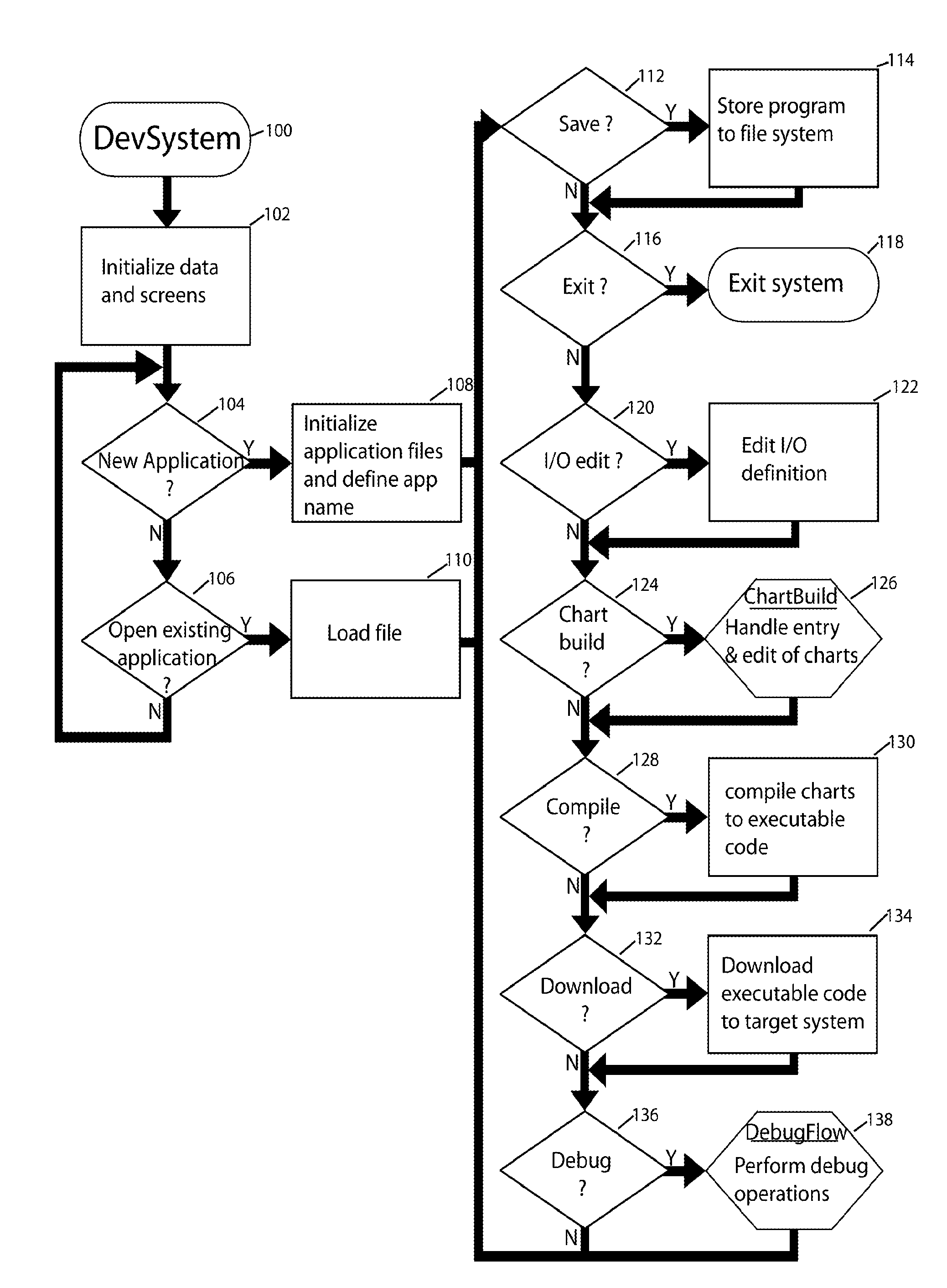
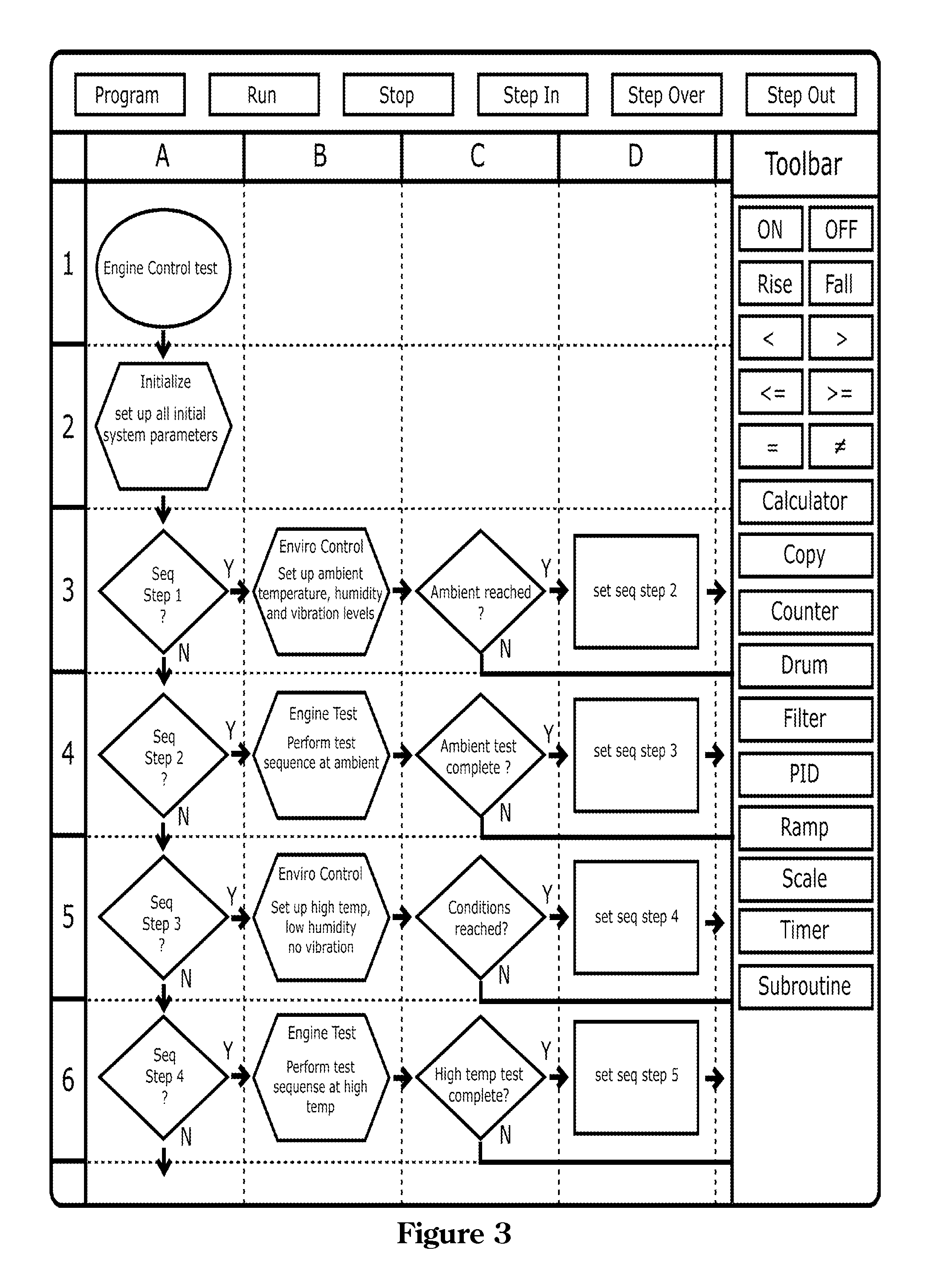
[0016]The purpose of this invention is the creation of a method which provides the user the ability to design, program, monitor and debug automated test and simulation systems through the use of graphical flow charts. The user should be provided a great deal of flexibility and visibility into system programming, monitoring, and debug of system applications. The invention also incorporates a method by which components of the user created program can be isolated and reused in other applications.
[0032]The solution significantly reduces development time, validation time, development and implementation costs.

Problems solved by technology

The largest problem with current automated test and simulation technology, has to do with software.
Current systems, designed in high level languages, like ‘C’, C++, Visual Basic or Java tend to be problematic in a number of key areas.
System applications, written in such standard high level languages tend to be difficult and time consuming to develop, in addition to being prone to program errors.
They yield resulting code that is cryptic to read and very difficult to validate conformance to the original specification.
Furthermore, propagating known good test code from application to application ranges from difficult to impossible, given the variability of test platforms.
The first problem comes from trying to translate the definition flow chart into executable code.
The second problem is in being able to review the code and clearly determine whether the code actually implements the intended operation.
As system complexity grows, the problem grows exponentially.
For complex system requirements, problems associated with software development and validation lead to significant uncertainty.
Uncertainty leads to risk.
Risk can translate to performance issues, ranging from minor to catastrophic failure in real application.
As system application requirements become more complex, software development becomes an increasingly significant cost component, and a leading factor in application development time.
Translating from clear, typically flow chart defined, specifications to executable code is a time consuming, error prone, difficult to validate process.
Flow chart programming has thus far shown insufficient advantages over the entrenched ladder logic programming technology to displace it in the field of automation.
The flow chart process and decision block structure is directly applicable to this type of operation, whereas other graphical systems, such as ladder logic, are poor representations and not well suited.

Method used


Image

  • Flow Chart Programming Platform for Testers and Simulators
  • Flow Chart Programming Platform for Testers and Simulators
  • Flow Chart Programming Platform for Testers and Simulators

Examples


Embodiment Construction

Conceptual Overview

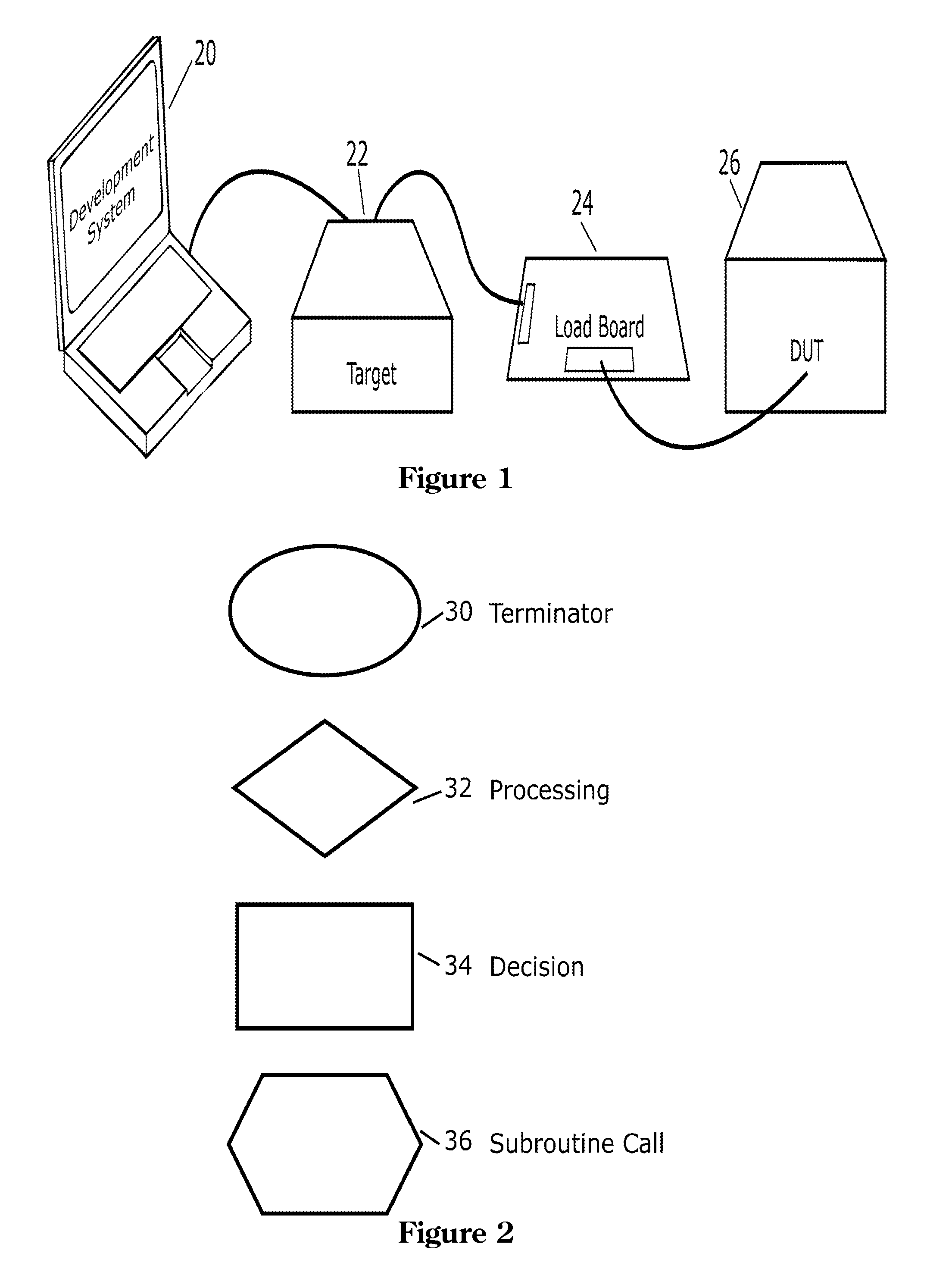
[0044]The concept for a design environment and execution platform that provides for the design, construction and programming of testers and simulators in efficient, reliable, low risk manner is outlined in the following text.

[0045]The graphical software programming solution:[0046]provides for application programming in a graphical, flow chart development language[0047]provides for debugging of application code from the development module.[0048]provides for the permanent deployment of finalized executable code to the execution platform.[0049]provides an architecture that easily enables the development of standard algorithms that can be reused.

[0050]With these software features, the major problems associated with current software technology can be eliminated. Systems built with the embodiment of this technology provide:[0051]greater efficiency in software development[0052]greatly simplified validation of code, due to the direct implementation of flow chart specifica...


PUM

PropertyMeasurementUnit
timeaaaaaaaaaa
stressaaaaaaaaaa
flexibilityaaaaaaaaaa

Abstract

A system for the development, compilation, execution, monitoring and debug of automated test and simulation systems in a flow chart programming language. A development and debug system, implemented as software on a computer, which provides an application developer the capability to enter fully defined application programs through the use of graphical flow charts. An executions system, implemented as a program on a device incorporating a central processing unit, memory, communications and necessary interfaces, which executes graphical flow charts compiled by the development and debug system. The development and debug system communicates with the execution system to download programs, control operation, monitor operation and provide a debugging environment.

Description

CROSS-REFERENCE TO RELATED APPLICATIONS[0001]This application claims the benefits of provisional patent application Ser. No. 61 / 409,256, filed on Nov. 2, 2010 by the present inventor.BACKGROUND[0002]1. Prior Art[0003]The following is a tabulation of some prior art that presently appears relevantU.S. PatentsPat. No.Kind CodeIssue DatePatentee4,852,047B1July 1989Lavalle et al.6,275,955B1August 2001Klein et al.6,421,821B1July 2002Lavalle6,243,857B1June 2001Logan, III et al.6,754,540B1June 2004McFarland et al.6,865,729B1March 2005McMillan et al.7,000,191B2February 2006Schmitt et al.7,302,676B2November 2007Schmitt et al.[0004]2. Background[0005]This invention relates to a method for designing, implementing and debugging of automated tests systems, automated simulation systems and similar real time systems. In particular, it relates to application development, programming, debug and monitoring through the use of graphical flow charts.[0006]Automated test systems are designed to put a devi...

Claims


Application Information

Patent Timeline
Patent Type & Authority Applications(United States)
IPC IPC(8): G06F9/44
CPCG06F8/34C07H21/00
Inventor SIERK, DENNIS ALLENSIERK, DUSTIN DONAVON
Owner VELOCIO NETWORKS
Learn More