This helps you quickly interpret patents by identifying the three key elements:
Problems solved by technology
Method used
Benefits of technology
Benefits of technology
[0009]The present invention has been made to solve the above problems occurring in the related art, and an object of the present invention is to provide an active constant power supply apparatus which can rectify power having various intensities and frequencies without using a high capacity condenser for a smoothing circuit which degrades the power factor of a circuit, and can stably supply effective constant power to a load.
[0019]Two paths are provided for the current passing through the power switch, one of the two paths is connected to a ground terminal, and a remaining one of the two paths is connected to the turn-off decider in such a manner that an amount of the current flowing to the ground terminal is greater than an amount of the current flowing to the turn-off decider to reduce power consumed through the turn-off decider.
[0026]As described above, the active constant power supply apparatus according to the present invention can rectify power having various intensities and frequencies without using a high capacity condenser for a smoothing circuit which degrades the power factor of a circuit, and can stably supply effective constant power to the load.
Problems solved by technology
In addition, the high voltage / capacitance condenser for the smoothing circuit Cd is very expensive and increases the size of the circuit so that the physical size of the constant power supply module may be enlarged.
Method used
Image
Click on the blue label to locate the original text in one second.
Reading with bidirectional positioning of images and text.
Examples
embodiment 1
[0092]Hereinafter, the active constant power supply apparatus according to the first embodiment of the present invention will be described with reference to accompanying drawings.
[0093]FIG. 9 is a schematic of the active constant power supply apparatus according to the first embodiment of the present invention.
[0094]As shown in FIG. 9, the active constant power supply apparatus according to the first embodiment of the present invention includes an AC power supplier 50, a rectifier 51, low pass filters LLPF and CLPF, a load 52, a driving coil L1, a free-wheeling diode D1, a power switch Q1, a resistor R1, a turn-off decider 80, a driving signal generator 101, a flip-flop 93, an AND logic 91 and a switch driver 92. The turn-off decider 80 includes an LEB (Leading Edge Blanker) 81, a Zener diode ZD1 to generate reference voltage, a comparator 82 and a pulse width controller (not shown).
[0095]The rectifier 51 is connected to an output terminal of the AC power supplier 50 to rectify the ...
experimental example 1
[0119]Hereinafter, the experimental examples of the active constant power supply apparatus according to the first embodiment of the present invention will be described with reference to FIG. 9.
[0120]The circuit shown in FIG. 9 is subject to the simulation test (serial No. A029) by using a computer. And the waveforms obtained from the simulation test are shown in FIG. 17. In the simulation test, the load 52 is prepared in the form of LED strings. If 20 mA is applied to the load 52, voltage at both terminals of the LED string is 50.3V. The load 52 is formed by connecting 40 LED strings in parallel and a load resistor having 10Ω is connected to each LED string in series.
[0121]The AC input voltage is 176VAC, which is 80.4% of 220VAC, the maximum rectifying voltage is 250V, the power frequency is 50 Hz. The filter coil LLPF is set to 2 mH. The filter condenser CLPF is set to 0.3 uH. The driving coil L1 is set to 320 uH. The driving frequency is 50 KHz. The driving pulse width is 3.8 μs, ...
embodiment 2
[0139]Hereinafter, an active constant power supply apparatus according to the second embodiment of the present invention will be described in detail with reference to accompanying drawings.
[0140]FIG. 20 is a schematic of the active constant power supply apparatus according to the second embodiment of the present invention.
[0141]According to the second embodiment of the present invention, the turn-off decider 80 is used as an auxiliary turn-off decider, which is operated only when a surge current, such as thunderbolt, occurs and does not operate under the normal input voltage. In detail, the power switch Q2 has the constant turn-on term in the one cycle of the input voltage and an additional gradient measurement circuit for adjusting the driving pulse width may serve as the turn-off decider 80 according to the first embodiment. The second embodiment of the present invention is suitable for the above-described three driving schemes.
[0142]That is, the second embodiment of the present i...
PUM
Abstract
Disclosed is an active constant power supply apparatus, which rectifies power having various intensities and frequencies without using a high capacity condenser for a smoothing circuit which degrades the power factor of a circuit, and supplies constant power to a load. The active constant power supply apparatus includes an AC power supplier for supplying AC power; a rectifying circuit which receives AC power from the AC power supply unit and rectifies the received power; a driving coil connected in series to the load receiving power from the rectifying circuit; a power switch which switches the current passing through the driving coil and the load on / off; a pulse-type driving signal generator connected to a gate terminal of the power switch to control the switching on / off operation of the power switch; a turn-off decider which generates a turn-off signal when the current flowing along the driving coil has a value higher than the designed value, so as to turn off the power switch; and a pulse width controller which measures the control periodranging from the switch-on time of the driving signal generator to the switch-off time of the turn-off decider, and controls the driving pulse width of the driving signal generator such that the driving pulse width coincides with the control period.
Description
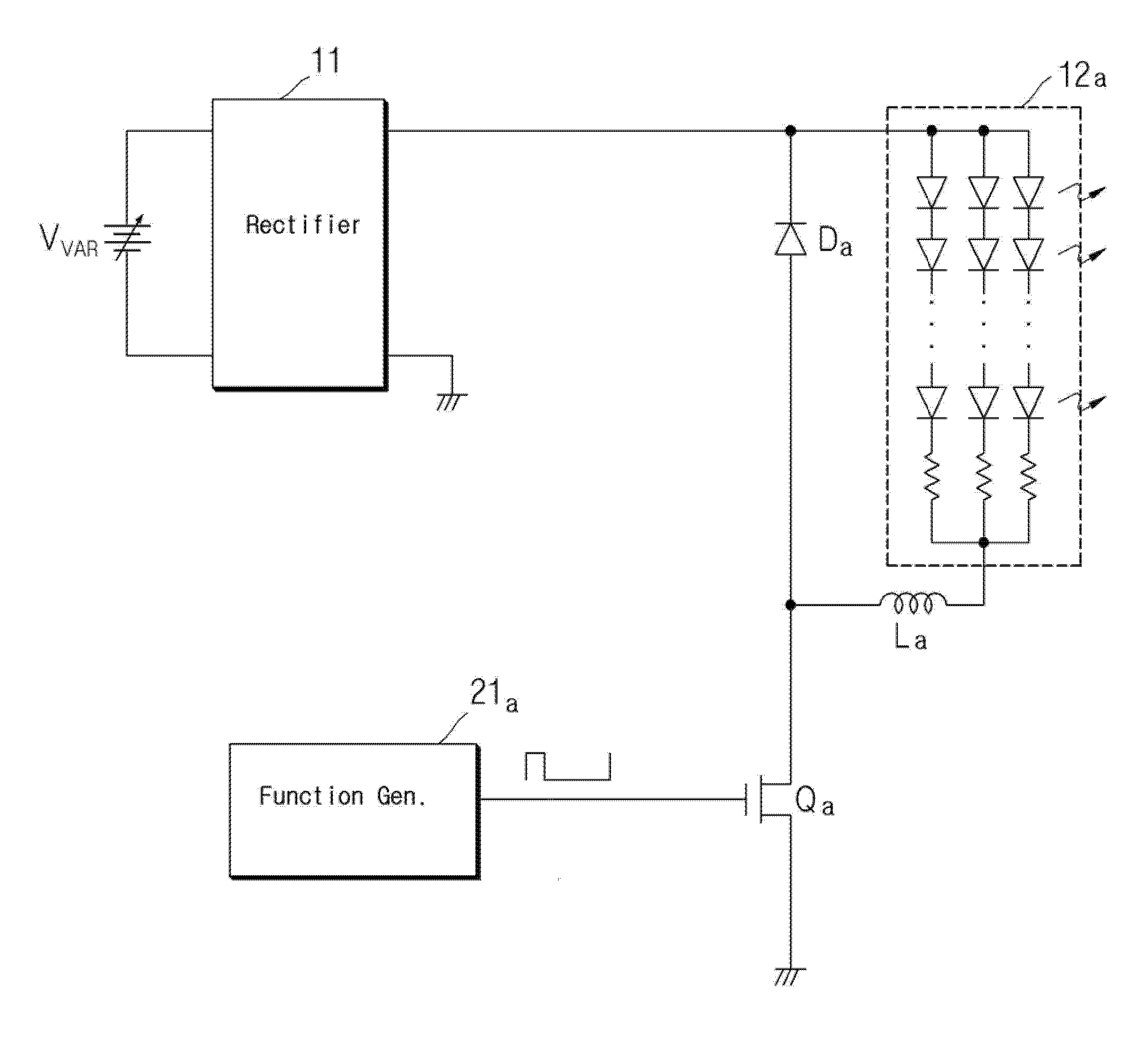
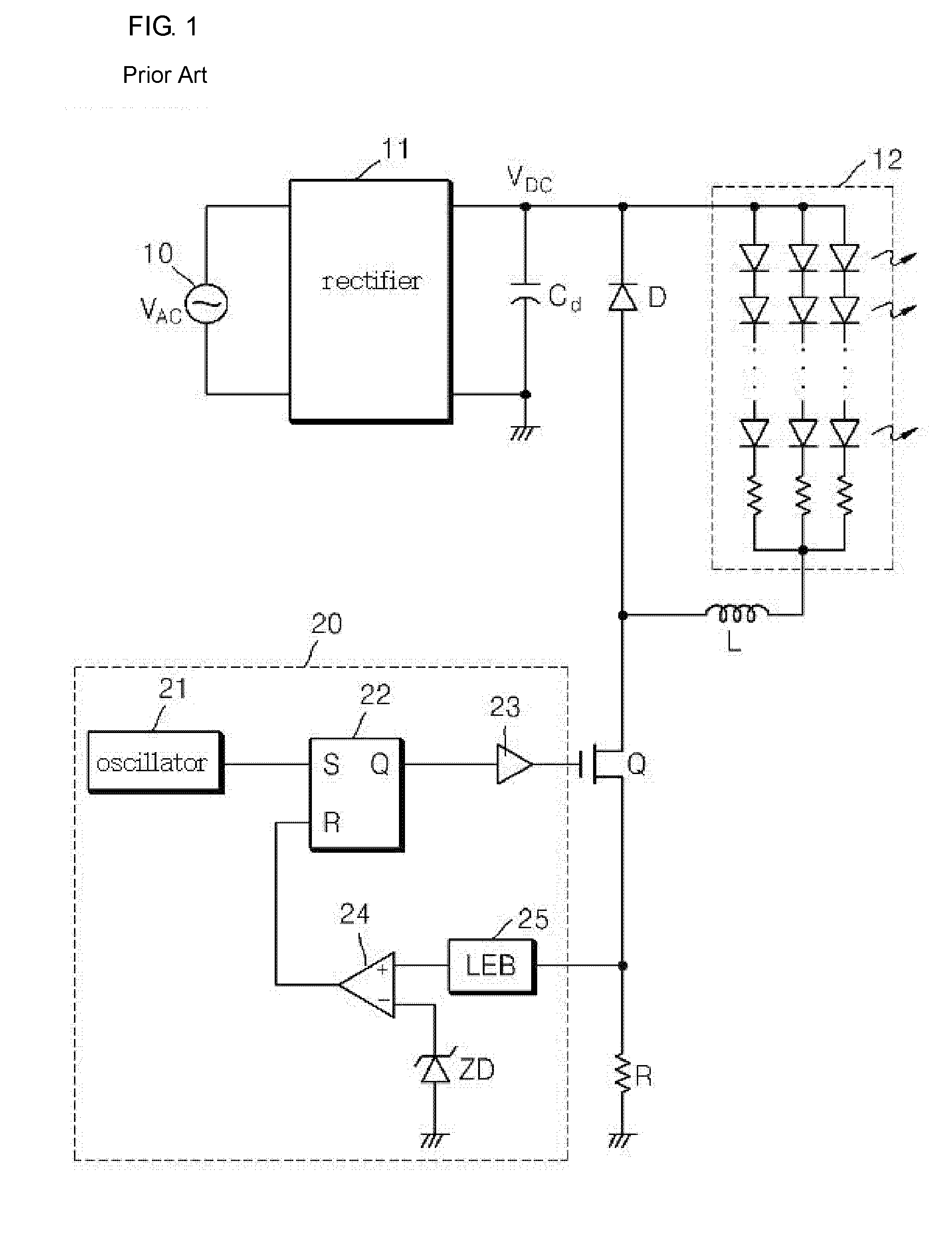
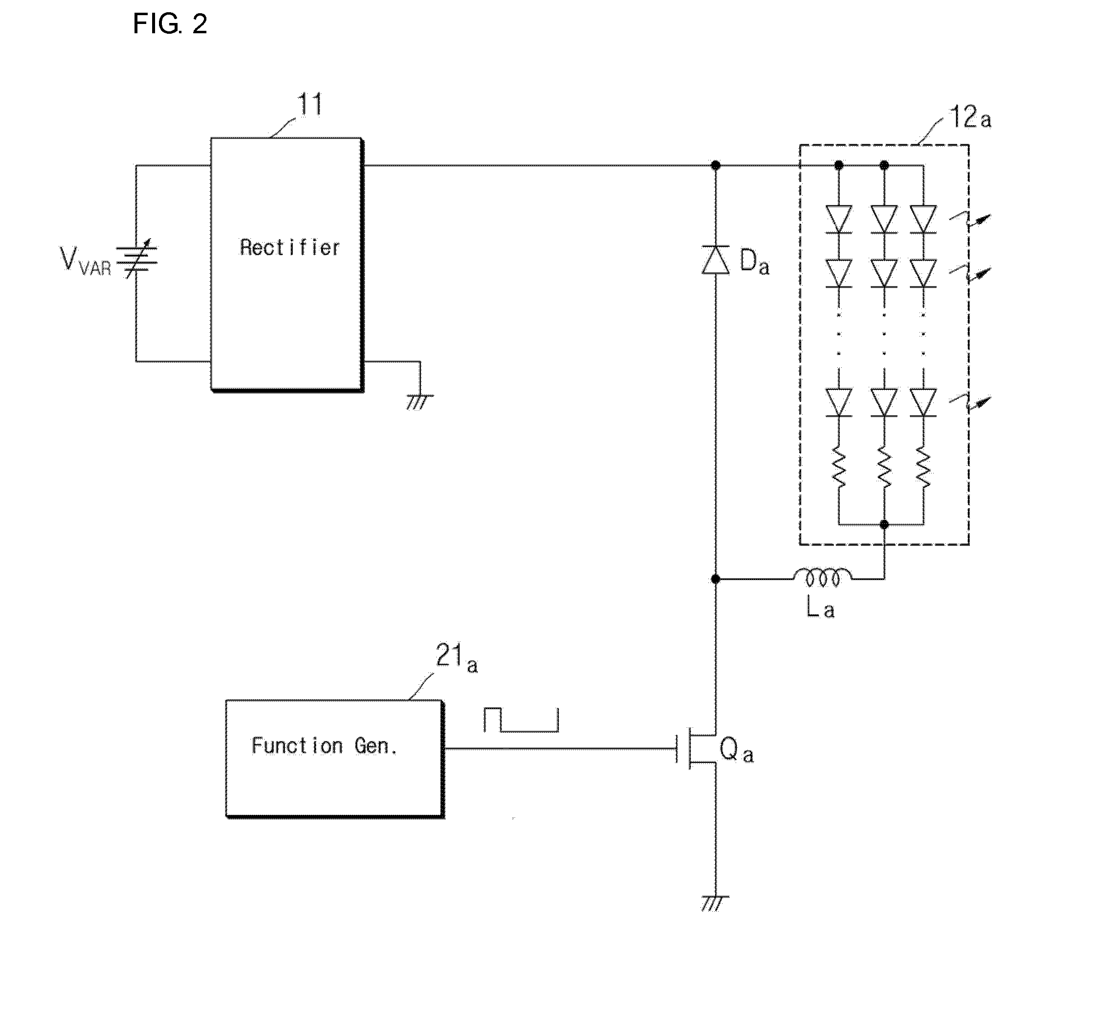
BACKGROUND OF THE INVENTION[0001]The present invention relates to an active constant power supply apparatus. More particularly, the present invention relates to an active constant power supply apparatus which can rectify power having various intensities and frequencies without using a high capacity condenser for a smoothing circuit which degrades the power factor of a circuit, and can supply constant power to a load.[0002]The precise control for power supply is very important in various fields. In particular, since current of an LED (light emitting diode) is significantly varied even if voltage is slightly changed, the precise current control is required.[0003]According to the related art, as shown in FIG. 1, AC power supplied from an AC power supplier 10 is converted into DC voltage by a rectifier 11 and a smoothing circuit Cd, and constant voltage is supplied to a load by a pulse width controller 20.[0004]In addition, under the designed input voltage of the AC power supplier 10, t...
Claims
Application Information
Patent Timeline
Application Date:The date an application was filed.
Publication Date:The date a patent or application was officially published.
First Publication Date:The earliest publication date of a patent with the same application number.
Issue Date:Publication date of the patent grant document.
PCT Entry Date:The Entry date of PCT National Phase.
Estimated Expiry Date:The statutory expiry date of a patent right according to the Patent Law, and it is the longest term of protection that the patent right can achieve without the termination of the patent right due to other reasons(Term extension factor has been taken into account ).
Invalid Date:Actual expiry date is based on effective date or publication date of legal transaction data of invalid patent.

