Battery pack balancing circuit

a battery pack and circuit technology, applied in the field of rechargeable batteries, can solve problems such as the inability to charge current, and achieve the effect of greater control of the cell balancing

Inactive Publication Date: 2012-05-17
TENERGY CORP
View PDF15 Cites 21 Cited by
  • Summary
  • Abstract
  • Description
  • Claims
  • Application Information

AI Technical Summary

Benefits of technology

[0009]The use of power transistors for the balancing current and a microcontroller responsive to state of...

Problems solved by technology

Additionally, an associated temperature measurement device may limit or disable the balancing current, as well...

Method used


Image

  • Battery pack balancing circuit
  • Battery pack balancing circuit
  • Battery pack balancing circuit

Examples


Embodiment Construction

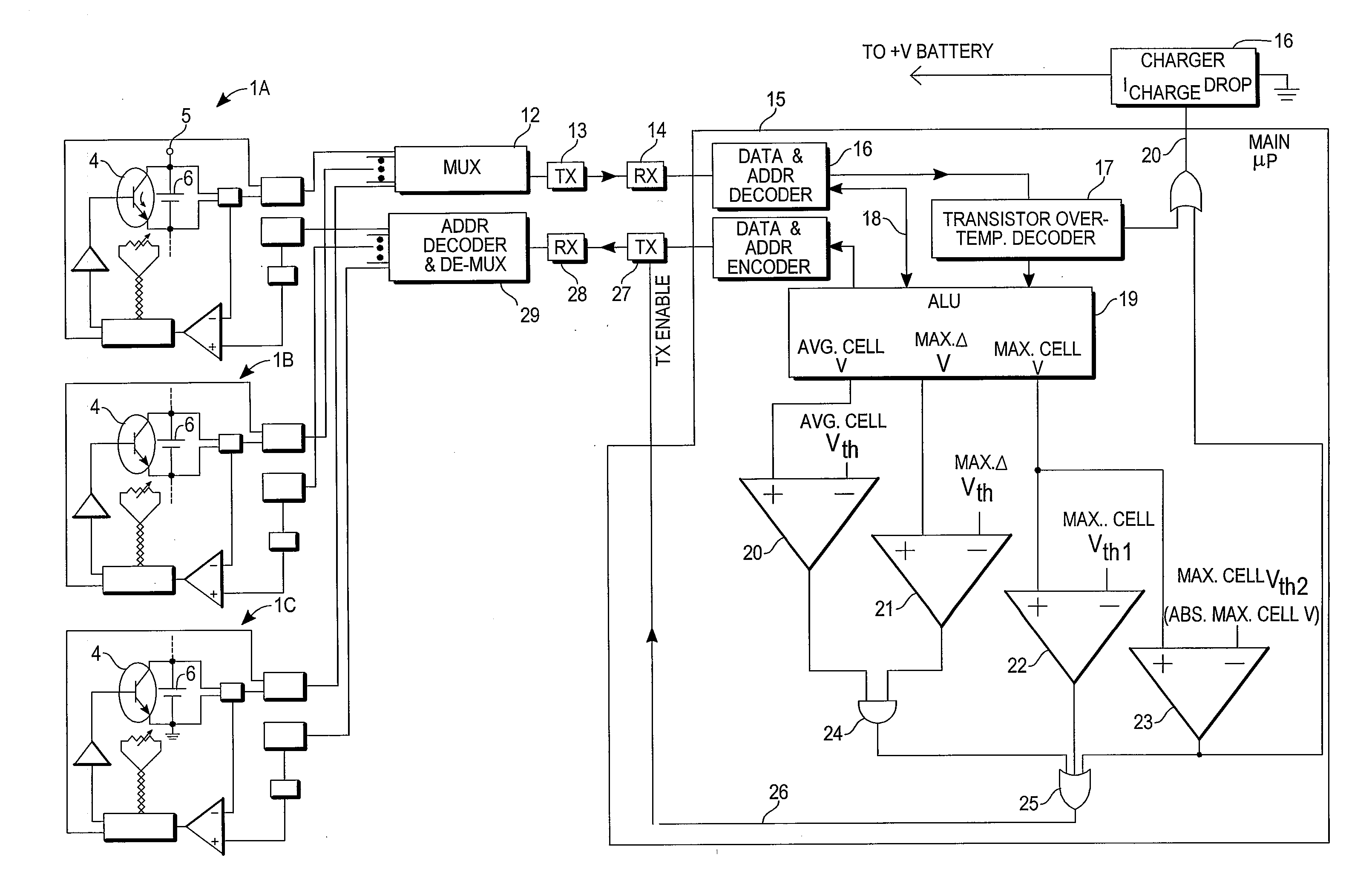
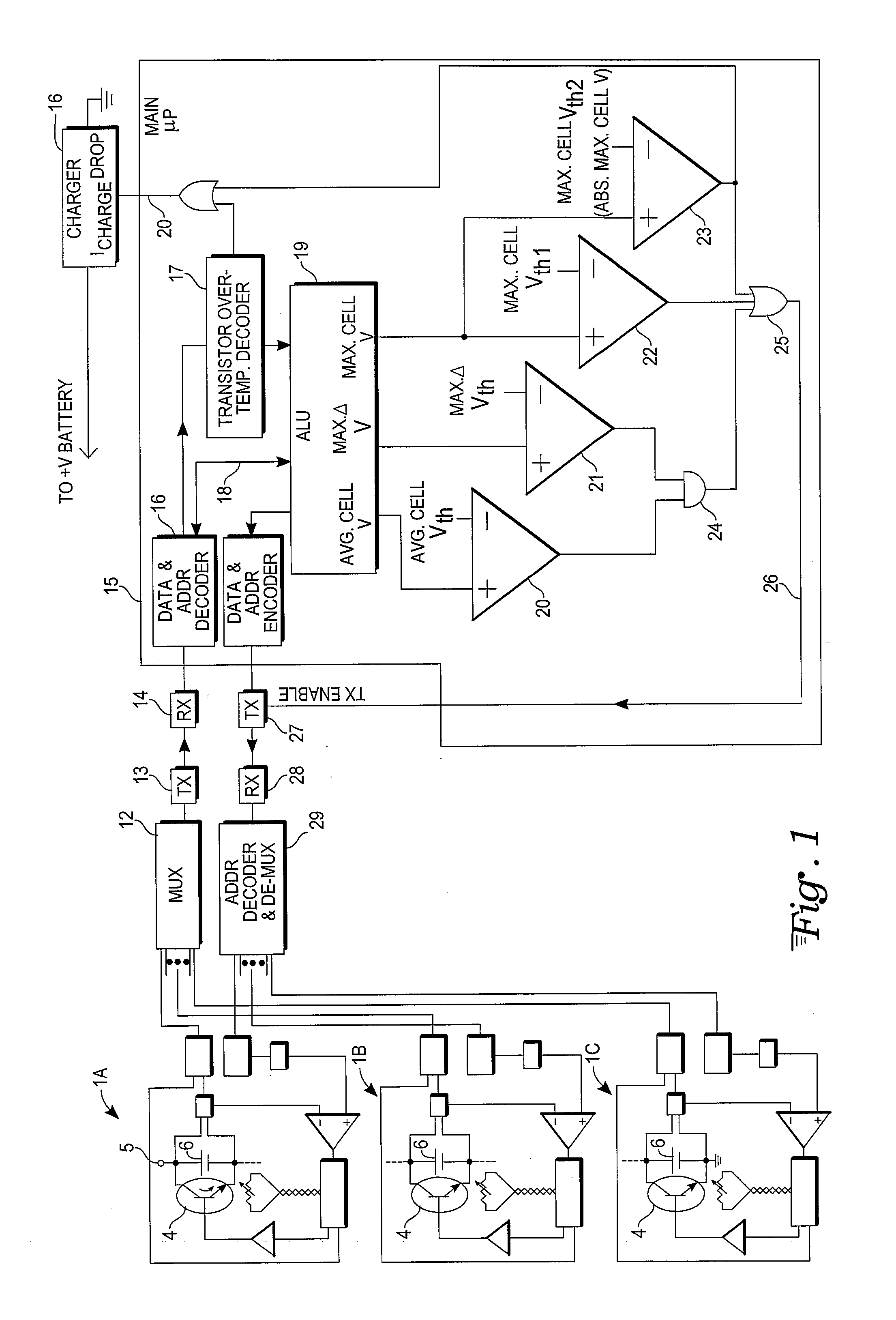
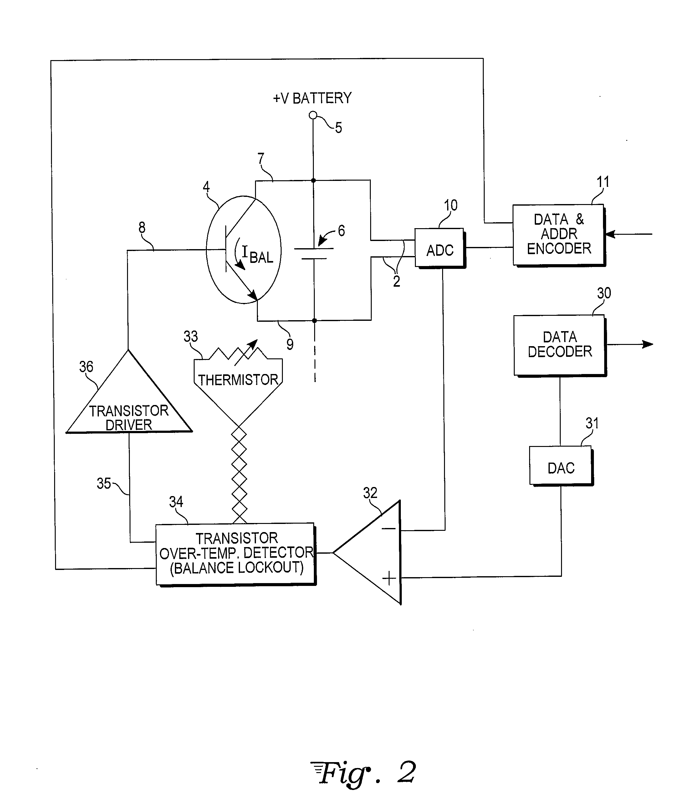
[0013]With reference to FIGS. 1 and 2, a battery management balancing device has microprocessor circuitry 15 that compares individual cell voltages and makes the battery management decisions for the cells 6 in a battery pack. The decisions of the microprocessor 15 are sent to battery balancing circuits 1A, 1B . . . 1C dedicated to the individual cells 6. The microprocessor 15 may also signal through a charger control output 20 to a charger 16 to slow or cease charging of the cells 6. Any number of cells 6 in series is theoretically possible. However, practical considerations of the application and voltage safety will limit the number of cells that will be connected in series.

[0014]The microprocessor circuitry 1 compares individual cell 6 voltages via any number of sensor leads 2 that are connected to every positive and negative cell 6 terminal in the battery pack. The analog voltage signals from the sensor leads 2 are converted to digital signals via analog-to-digital converters (AD...


PUM


Abstract

A battery management balancing device provides local discharge circuits for individual cells of a battery pack, where the discharge circuits include a power transistor. The use of a power transistor yields a controllable balancing current through that transistor between a cathode and anode of the individual cell. A microcontroller monitors a state of charge of each cell, such as by measuring the cell voltages, and provides control signals, for example indicating a target voltage for each cell, that drive the power transistors in designated discharge circuits.

Description

CROSS-REFERENCE TO RELATED APPLICATION[0001]The present invention claims priority under 35 U.S.C. 119(e) from prior U.S. Provisional Application No. 61 / 414,609, filed Nov. 17, 2010.TECHNICAL FIELD[0002]The present invention relates to rechargeable batteries and specifically to circuit arrangements or systems for battery charging or discharging, as in charger structures for battery packs, as well as battery management systems, and more particularly to battery balancing devices that balance the state of charge of individual cells in a battery pack.BACKGROUND ART[0003]Battery balancing is a technique used to equalize the state of charge of individual cells in a battery pack (comprised of series-connected cells). Typically, the various cells when manufactured have slightly different storage capacities and states of charge. Also, the battery pack may become unbalanced over time from repeated cycles of charging and discharging due to differences in internal impedance. A battery's characte...

Claims


Application Information

Patent Timeline
IPC IPC(8): H02J7/00
CPCH02J7/0016
Inventor MULL, BENJAMIN C.KASPARIAN, HRAG
Owner TENERGY CORP
Why Eureka
Try Eureka