Butyl-free freezer panel joints

a technology of freezer panel joints and butyl sealants, which is applied in the direction of domestic cooling devices, lighting and heating devices, washing machines, etc., can solve the problems of sticky and messy application and service, butyl sealants are not without their problems, and the application and service of sticky and messy materials is not easy

a technology of freezer panel joints and butyl sealants, which is applied in the direction of domestic cooling devices, lighting and heating devices, washing machines, etc., can solve the problems of sticky and messy application and service, butyl sealants are not without their problems, and the application and service of sticky and messy materials is not easy

US20120121322A1Inactive Publication Date: 2012-05-17KYSOR PANEL SYST DIV OF WELBILT WALK INS

Image

  • Butyl-free freezer panel joints
  • Butyl-free freezer panel joints
  • Butyl-free freezer panel joints

Examples


Embodiment Construction

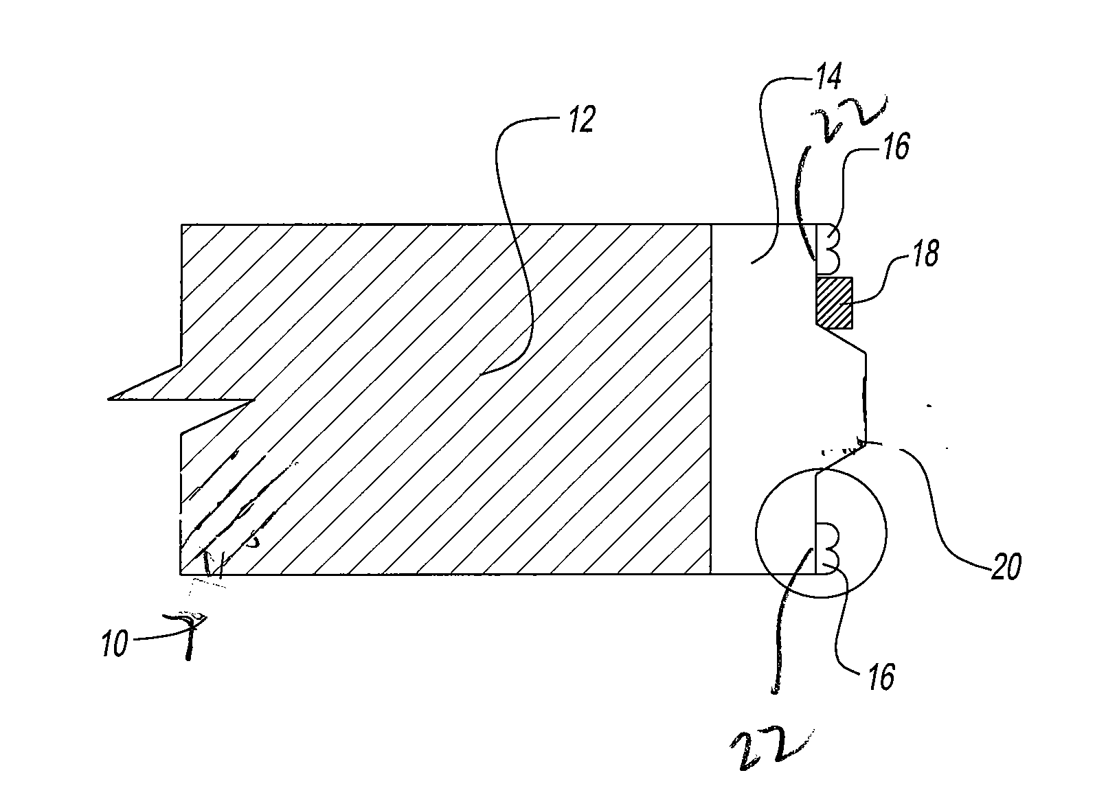
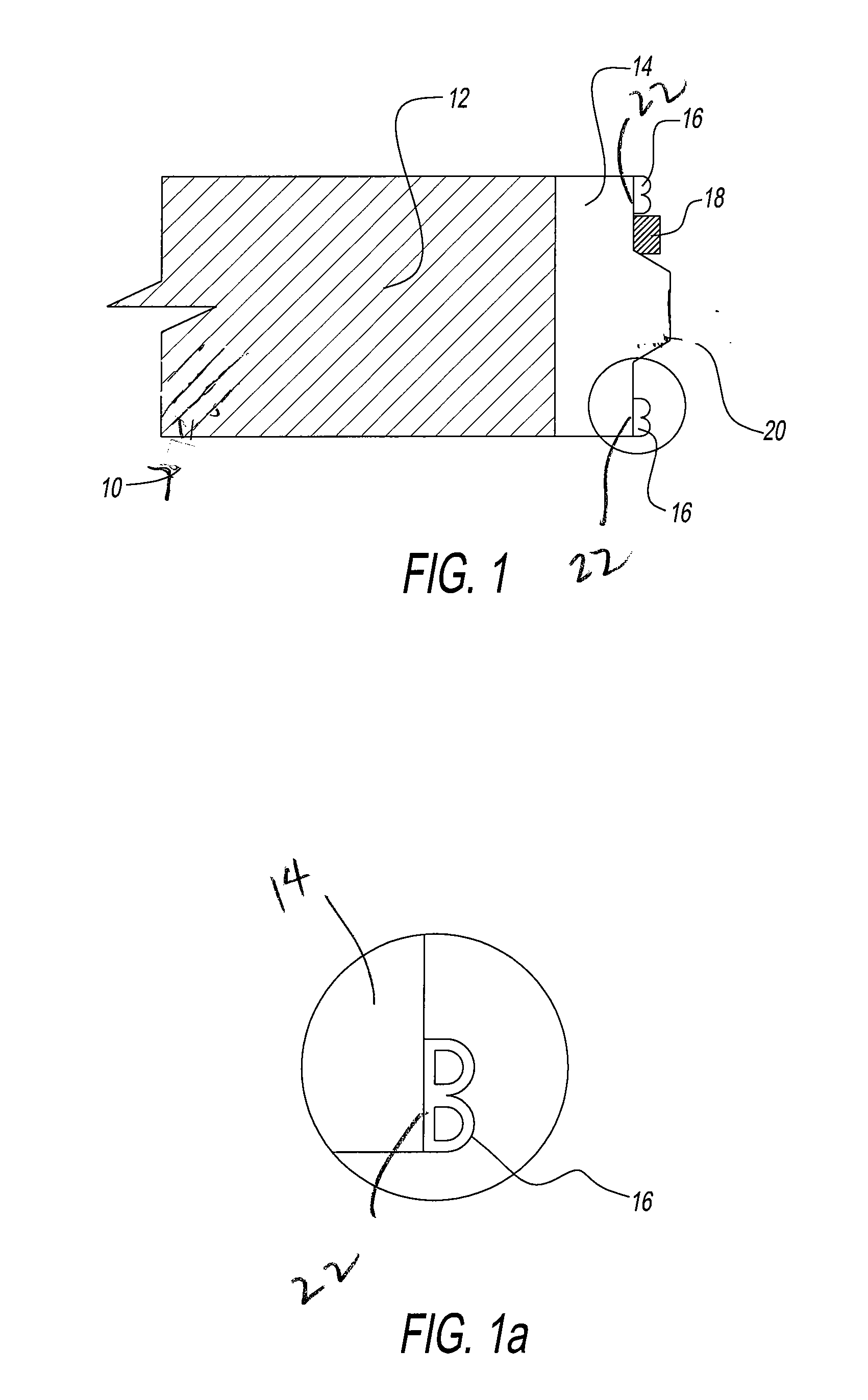
[0028]This disclosure can best be described by referring to the figures wherein FIG. 1 is a schematic representation with portions broken away of a freezer panel joint assembly 10 having an insulation panel 12 and a framing member 14, in turn having tongue or male portion 20 of a tongue and groove panel joint with the first gaskets 16 disposed on opposite sides of tongue portion 20 and further having a second gasket 18 disposed between tongue portion 20 and one of first gaskets 16. In particular, FIG. 1 depicts a broken away portion of a insulation panel 12 which shows the panel edge of or vertical cross section therethrough. FIG. 1 shows: (1) an edge of or vertical section through framing member 14, including through tongue portion 20 of the framing member vertical section lines through framing member 14, not shown); (2) a vertical section through a first gasket 16; and (3) a vertical section through a second gasket 18 (highly shaded), that lies along and above tongue portion 20, b...


PUM


Abstract

A butyl-free freezer panel joint is obtained by use of at least a first compressible gasket of polyvinyl chloride disposed about the tongue of a tongue and groove panel joint, and the use of a second compressible gasket that is an adhesive-like material that lies between the first gasket and the tongue portion of the framing member of the panel joint.

Description

CROSS-REFERENCED APPLICATION[0001]This non-provisional U.S. patent application is related to and claims the benefit of U.S. provisional application Ser. No. 61 / 413,955, filed Nov. 15, 2010, which is incorporated herein in its entirety by reference thereto.BACKGROUND[0002]1. Field of the Disclosure[0003]This disclosure relates generally to the field of butyl-free freezer panel joints. The disclosure also relates to butyl-free freezer panel joint assemblies comprised of an assemblage or fitting together of freezer panel joints and panels into complete walls, panels, structures or units. The joint assemblies seal the joints of freezer panels using, inter alia, a multi-component gasket that functions well as a sealant without the need for or use of a butyl sealant.[0004]2. Discussion of Background Art[0005]For many years, sealants for joining freezer and other panels have included butyl or butyl-containing materials, herein sometimes referred to “butyl sealants”. These materials have pr...

Claims


Application Information

Patent Timeline
17 May 2012
Publication
US20120121322A1
IPC
F16B5/00
CPC
Y10T403/52; F25D23/063; F16B2200/60
Inventors
MINELLI, FRED L.