Rotor for a turbo machine

a technology of rotating blades and rotating wheels, which is applied in the direction of climate sustainability, air transportation, leakage prevention, etc., can solve the problem of not being able to provide optimal cooling air for rotating blades, and achieve the effect of improving the supply of cooling air

Inactive Publication Date: 2012-05-17
MTU AERO ENGINES GMBH
View PDF17 Cites 8 Cited by
  • Summary
  • Abstract
  • Description
  • Claims
  • Application Information

AI Technical Summary

Benefits of technology

[0006]The object of the invention is to make possible an improved prov

Problems solved by technology

Viewed as a disadvantage in the known rotor, however, is the circumstance that an optimal supply of cooling air for the rotating blades is not made possible, since the geometries of the inlet openings are the cause of grea

Method used


Image

  • Rotor for a turbo machine
  • Rotor for a turbo machine
  • Rotor for a turbo machine

Examples


Embodiment Construction

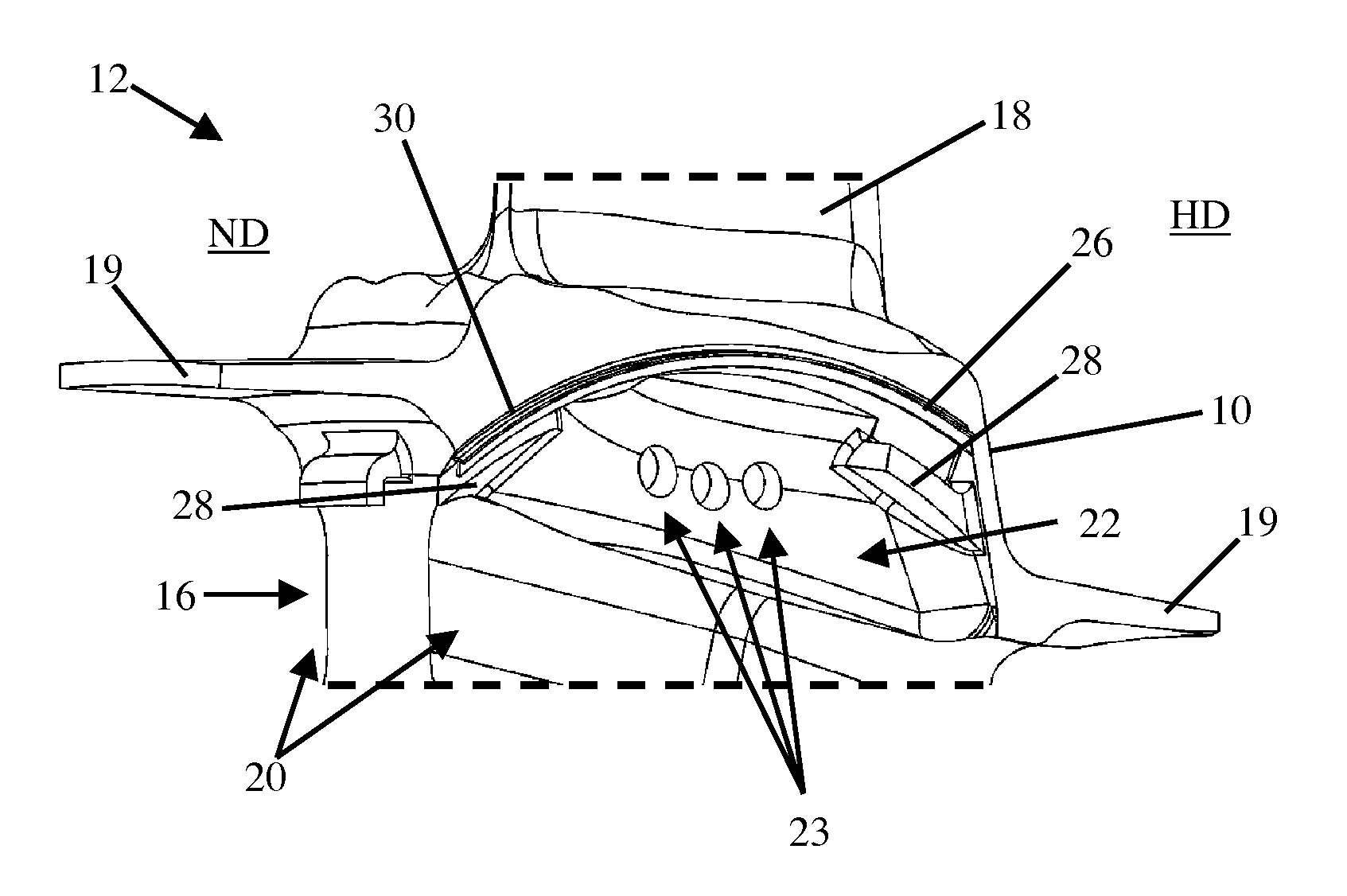
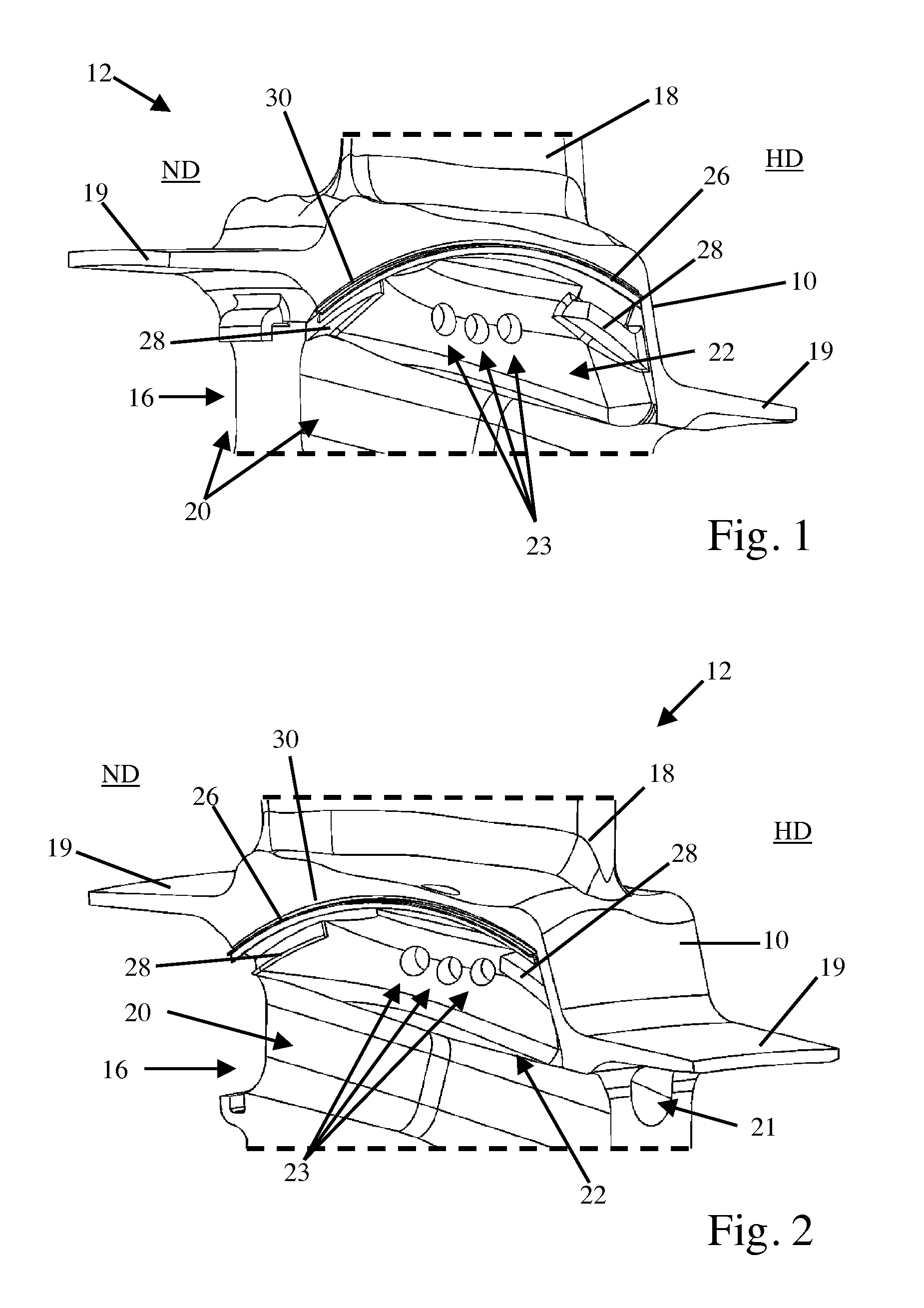
[0025]FIG. 1 shows a schematic perspective view of a rotating blade 12 seen from the low-pressure (ND) side of a rotor (not shown). FIG. 1 will be explained in the following in conjunction with FIG. 2, in which a schematic perspective view of the rotating blade 12 shown in FIG. 1 is illustrated, viewed from the high-pressure (HD) side of the rotor.

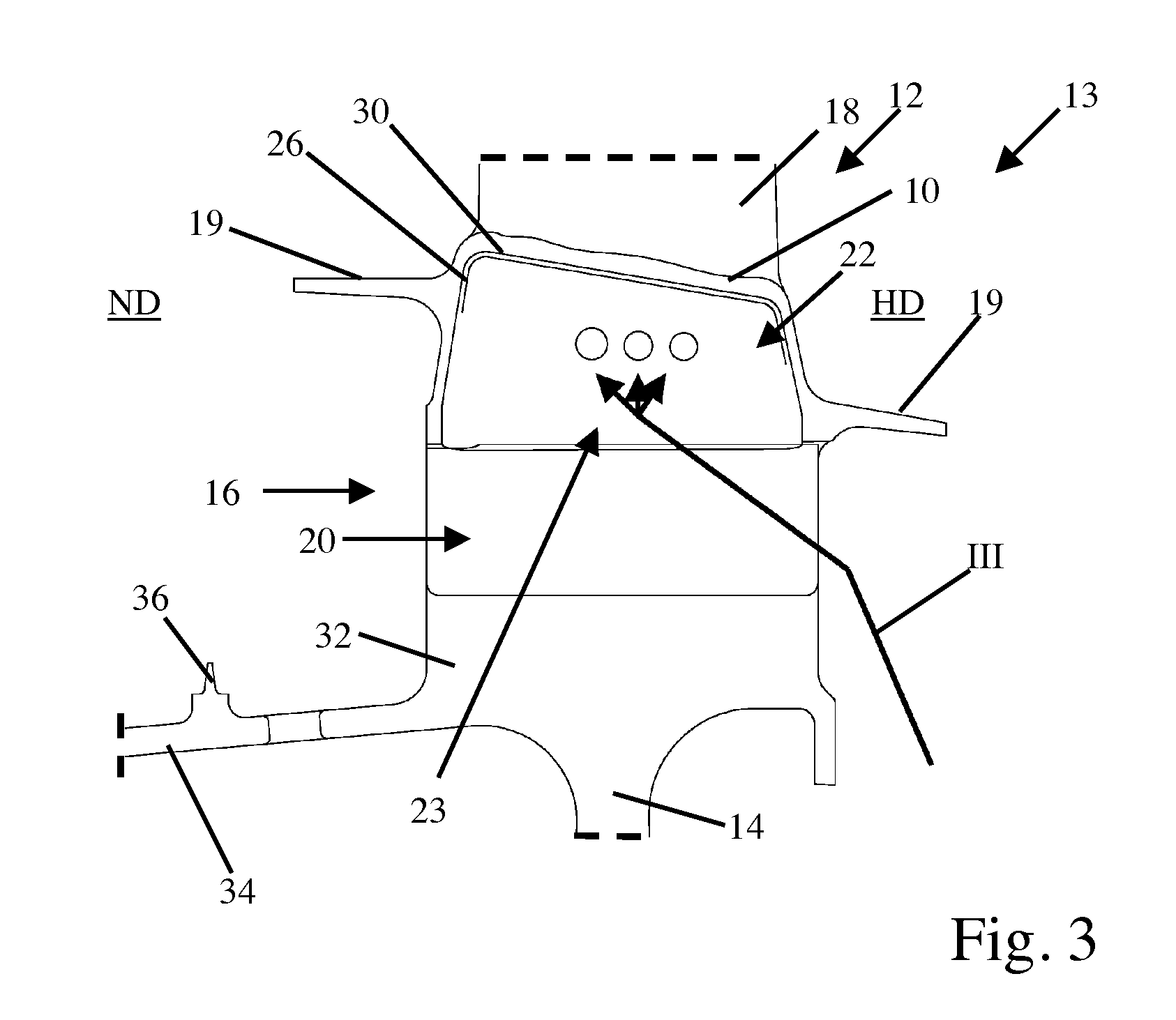
[0026]The rotor, which is designed presently in integral BLISK (Bladed Disk) construction for a turbine stage of an aircraft engine, comprises a basic rotor body 14 (see FIG. 3), which is joined cohesively in a way known in and of itself to several rotating blades 12. A radially inner region (relative to an axis of rotation of the rotor) of a blade element 18 connecting to a blade platform 10 can be recognized in FIG. 1 for the illustrated rotating blade 12. Blade platform 10, together with projections formed on the low-pressure (ND) side and the high-pressure (HD) side of the rotor, forms a blade shroud 19 for the at least partial boundar...


PUM

PropertyMeasurementUnit
Pressureaaaaaaaaaa

Abstract

The invention relates to a rotor (13) for a turbo machine, in particular for an aircraft turbine, having rotating blades (12), which are joined to a basic rotor body (14), in which at least one rotating blade (12) has at least one inner cooling channel, which extends at least along a predominant region of a blade element (18) of rotating blade (12) and has an inlet opening (23) for introducing cooling air into blade element (18), in which the inlet opening (23) is formed in a blade neck (16) lying between a blade foot (32) and a blade platform (10) of rotating blade (12). Inlet opening (23) is disposed in a cavity (22) formed radially underneath blade platform (10). In addition, the invention relates to a blade or vane, in particular a rotating blade (12) for a rotor (13) of a turbo machine, as well as a turbo machine.

Description

BACKGROUND OF THE INVENTION[0001]The invention relates to a rotor of the type indicated in the preamble of patent claim 1, a blade or vane of the type indicated in the preamble of patent claim 12 as well as a turbo machine having a rotor.[0002]In turbo machines, such as aircraft turbines, for example, which are used in a number of variants in aircraft, but also in different types of aircraft and in stationary applications, continually higher temperatures are targeted in the one or more internal combustion chambers, in order to obtain an improved efficiency. In the high-pressure part of the aircraft turbine that is connected downstream of the internal combustion chamber, all open surfaces of guide vanes and rotating blades as well as other components that lay open are therefore subjected to temperatures that can lie partially in the region of the melting point of the materials used. In order to be able to operate an aircraft turbine at a temperature that is as high as possible, the c...

Claims


Application Information

Patent Timeline
IPC IPC(8): F01D5/18
CPCF01D5/22F01D11/006F04D29/321F04D29/668Y10T29/49318Y02T50/673Y02T50/676F01D5/187Y10T29/49321Y02T50/671Y02T50/60
Inventor BORUFKA, HANS PETERSTIEHLER, FRANK
Owner MTU AERO ENGINES GMBH
Why Eureka
Try Eureka