Multicolor light emitting diode lamp for plant growth, illumination apparatus, and plant growth method

a light-emitting diode lamp and plant technology, applied in lighting and heating apparatus, lighting support devices, light source combinations, etc., can solve the problems of increasing the cost, and difficult to irradiate blue and red light uniformly

Active Publication Date: 2012-05-24
RESONAC CORP
View PDF14 Cites 45 Cited by
  • Summary
  • Abstract
  • Description
  • Claims
  • Application Information

AI Technical Summary

Benefits of technology

[0036]According to the plant growth method of the present invention, it is possible to control a combination of the number of light emitting diode lamps lit, the photon flux, the applied electric current, and the

Problems solved by technology

In this way, in order to realize an optimum light source for plant growth, since a small number of blue light emitting diodes are interspersed among a large number red light emitting diodes, it was difficult to irradiate blue and red light uniformly.
However, in the technique disclosed in PTL 2, there is a problem in that it is difficult to irradiate blue and red light uniformly.
However, in order to uniformly irradiate plants with blue and red light, in an illumination app

Method used


Image

  • Multicolor light emitting diode lamp for plant growth, illumination apparatus, and plant growth method
  • Multicolor light emitting diode lamp for plant growth, illumination apparatus, and plant growth method
  • Multicolor light emitting diode lamp for plant growth, illumination apparatus, and plant growth method

Examples


first embodiment

[0049]The configuration of a multicolor light emitting diode lamp for plant growth (hereinafter simply referred to as a “light emitting diode lamp”) according to an embodiment to which the present invention is applied will be described.

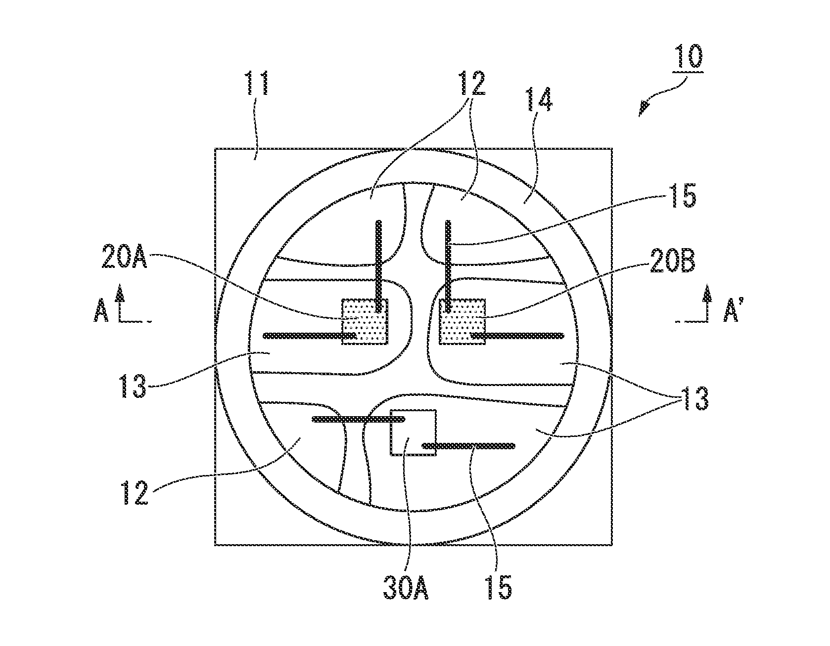
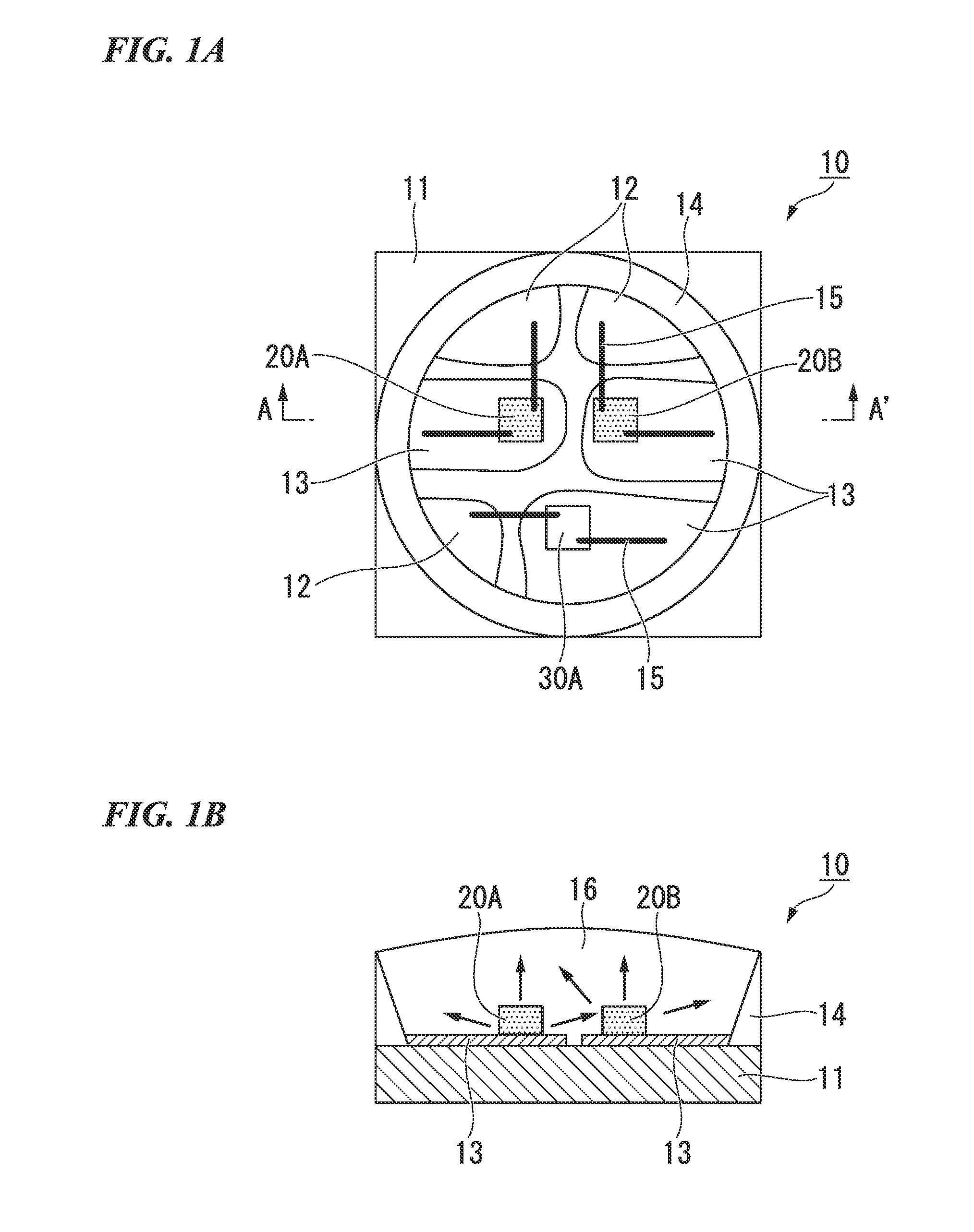
[0050]As shown in FIGS. 1A and 1B, a light emitting diode lamp 10 of the present embodiment is schematically configured such that three light emitting diodes 20A, 20B, and 30A are independently mounted on the surface of a mount substrate 11. More specifically, the light emitting diodes 20A and 20B (first light emitting diode) are red light emitting diodes in which a peak luminescence wavelength is not less than 655 nm and not more than 675 nm, and the light emitting diode 30A (second light emitting diode) is a blue light emitting diode in which a peak luminescence wavelength is not less than 420 nm and not more than 470 nm.

[0051](Red Light Emitting Diode)

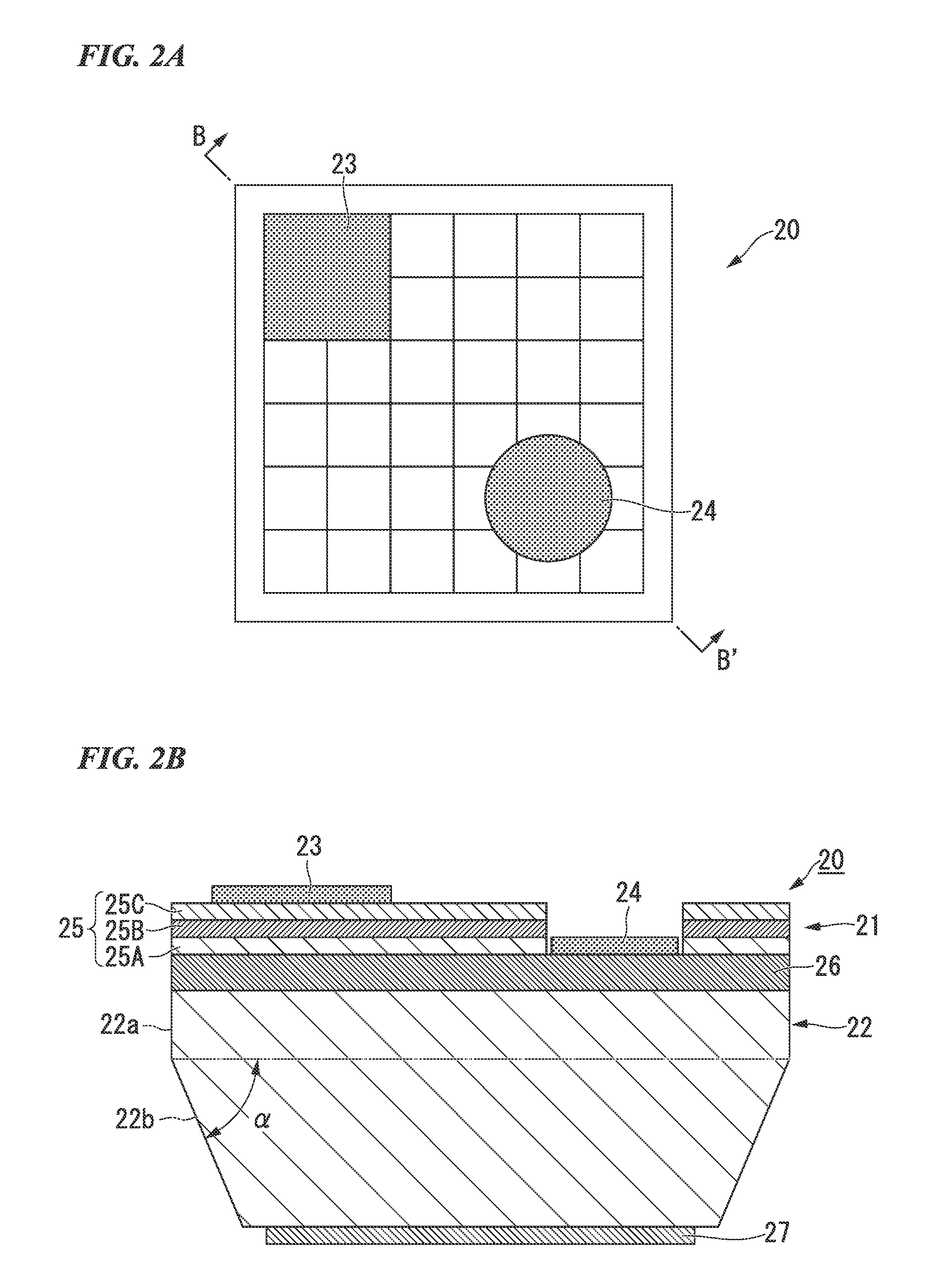
[0052]Here, the configuration of the red light emitting diodes 20A and 20B which each are the firs...

second embodiment

[0135]Next, a second embodiment to which the present invention is applied will be described. In the present embodiment, a light emitting diode lamp has a different configuration from the light emitting diode lamp 10 of the first embodiment. Thus, with regard to the configuration of the light emitting diode lamp of the present embodiment, the same constitutent portions as the light emitting diode lamp 10 of the first embodiment will be denoted by the same reference signs, and redundant description thereof will not be provided.

[0136]As shown in FIGS. 5A and 5B, a light emitting diode lamp 210 of the present embodiment is schematically configured such that five light emitting diodes 220A, 220B, 220C, 220D, and 230A are mounted on the surface of a mount substrate 211.

[0137]Here, in the light emitting diode lamp 10 of the first embodiment, the three mounted light emitting diodes 20A, 20B, and 30A are electrically independent. In contrast, in the light emitting diode lamp 210 of the prese...

third embodiment

[0146]Next, a third embodiment to which the present invention is applied will be described. In the present embodiment, a light emitting diode lamp has a different configuration from the light emitting diode lamps 10 and 210 of the first and second embodiments. Thus, with regard to the configuration of the light emitting diode lamp of the present embodiment, the same constitutent portions as the light emitting diode lamps 10 and 210 of the first and second embodiments will be denoted by the same reference signs, and a redundant description thereof will not be provided here.

[0147]As shown in FIGS. 6A and 6B, a light emitting diode lamp 310 of the present embodiment is schematically configured such that five light emitting diodes 320A, 320B, 320C, 330A, and 330B are mounted on the surface of a mount substrate 311.

[0148]Here, the light emitting diode lamps 10 and 210 of the first and second embodiments are driven by a direct-current power supply. In contrast, the light emitting diode la...


PUM


Abstract

In an illumination apparatus for plant growth using LEDs, a light source emitting mixed color light of red and blue is dominant light source. However, actually, the luminescence intensity of red light is weaker than that of blue light, and the color is adjusted by the number of lamps used. Thus, a small number of blue LEDs are interspersed among a large number of red LEDs, and there is a problem in that it is not possible to make irradiation of blue light uniform. The present invention provides a multicolor light emitting diode lamp in which a blue LED and a AlGaInP-based red LED having high luminescence efficiency, balancing with the blue LED are mounted in the same package. The red LED includes a light emitting section including a light emitting layer having a composition formula, (AlXGa1-X)YIn1-YP (0≦X≦1 and 0<Y≦1). The red LED emits at least as many photons as the blue LED when the same electric current is flowed. For example, when a strong red light is desirable for plant growth, by mounting two red LEDs and one blue LED, a desired mixed color is obtained with one lamp, and irradiation of light can be made uniform.

Description

TECHNICAL FIELD[0001]The present invention relates to a multicolor light emitting diode lamp for plant growth, an illumination apparatus, and a plant growth method.[0002]Priority is claimed on Japanese Patent Application No. 2009-184569, filed Aug. 7, 2009, the content of which is incorporated herein by reference.BACKGROUND ART[0003]In recent years, plant growth using an artificial light source has been studied. In particular, attention is being paid to a cultivation method using an illumination by a light emitting diode (LED) which has excellent monochromaticity and in which energy saving, long service life, and a reduction in size are possible.[0004]From previous study results, as one luminescence wavelength suitable for a light source for plant growth (photosynthesis), the effects of blue light having a wavelength around 450 nm and red light having a wavelength range of 600 nm to 700 nm have been confirmed. In particular, with respect to photosynthesis, light having a wavelength ...

Claims


Application Information

Patent Timeline
IPC IPC(8): A01G1/00F21V21/00
CPCA01G7/045H01L25/0753H01L2224/49175H01L2224/45144H01L2924/00F21Y2115/10F21Y2113/10F21Y2113/13Y02P60/14A01G7/00A01G7/04
Inventor TAKEUCHI, RYOUICHI
Owner RESONAC CORP
Why Eureka
Try Eureka