Refrigeration plant with refrigerant evaporator arrangement and process for parallel air and battery contact cooling

a refrigerant evaporator and battery technology, which is applied in the direction of domestic cooling apparatus, lighting and heating apparatus, electrochemical generators, etc., can solve the problems of uneven mass distribution, increased flow resistance in this flow path, and uneven distribution of vapor proportions over the flow cross-section, so as to reduce the load and improve the life of the battery cells. , the effect of slowing down the aging of the battery cells

Active Publication Date: 2012-05-24
HANON SYST
View PDF32 Cites 38 Cited by
  • Summary
  • Abstract
  • Description
  • Claims
  • Application Information

AI Technical Summary

Benefits of technology

[0015]According to the concept, the throttling of the refrigerant downstream of the battery cooler causes the liquid refrigerant to be impounded in the battery cooler. This results in a more homogeneous distribution of the refrigerant which, in effect, will have a positive impact.
[0038]Further advantages particularly of the invention are the reduction of the overheat zone of an overheat controlled evaporator, the even refrigerant division onto parallel switched evaporators and the flow paths within the evaporator, and the generation of different evaporation temperatures in multi evaporator plants.

Problems solved by technology

First, dividing the refrigerant mass flow supplied to the evaporators even for a symmetrical design leads to a slight unevenness in the mass distribution due to minor differences in the flow resistances of the individual flow paths.
However, due to overheating, the flow resistance in this flow path will increase.
Second, normally at the exit of the evaporators there is a diphase mixture with a low vapor proportion, but the vapor proportion is not evenly distributed over the flow cross-section.
Another disadvantageous effect if the battery and vehicle coolers are operated in parallel is that a clearly higher refrigeration power is required when the drive batteries are dynamically cooled compared to the stationary cooling load due to the electric losses.
The high refrigeration power in case of dynamic battery cooling causes an undesired high temperature spread in the battery cells due to the relatively bad heat conduction in the cells.
The high temperature spread has a negative effect on the life of the battery cells.
Further, the overheating at the exit of the battery cooler causes the refrigerant temperature to increase, hence, an uneven temperature distribution at the surface of the battery cooler.
This unevenness in the temperature distribution, due to bad heat conduction in the battery cells, reappears in the cells.

Method used


Image

  • Refrigeration plant with refrigerant evaporator arrangement and process for parallel air and battery contact cooling
  • Refrigeration plant with refrigerant evaporator arrangement and process for parallel air and battery contact cooling
  • Refrigeration plant with refrigerant evaporator arrangement and process for parallel air and battery contact cooling

Examples


Embodiment Construction

[0046]The following detailed description and appended drawings describe and illustrate an exemplary embodiment of the invention. The description and drawings serve to enable one skilled in the art to make and use the invention, and are not intended to limit the scope of the invention in any manner.

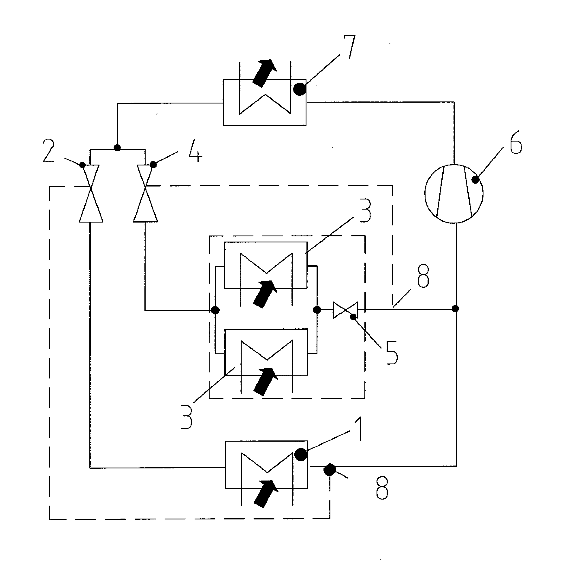
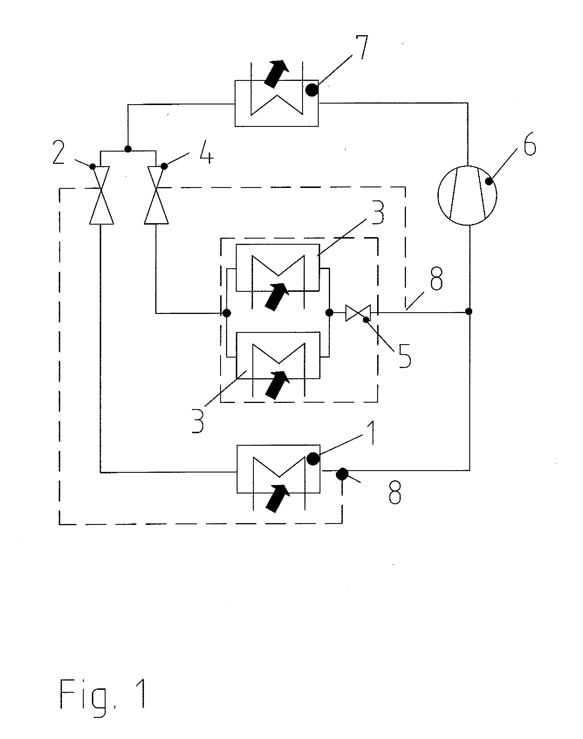
[0047]FIG. 1 shows a schematic circuit diagram of a refrigeration plant according to one embodiment of the invention with the relevant technical components. The main element of every refrigeration plant is the compressor 6 that compresses the gaseous refrigerant to the condensation pressure, and delivers it to the condenser 7. In the condenser 7, the refrigerant condenses to the condensation pressure level releasing heat, which is schematically indicated by an arrow in FIG. 1. The condensed, liquefied refrigerant reaches a branching point where the refrigerant mass flow is divided into a refrigerant partial mass flow for the cooling of the passenger compartment and a refrigerant partial ma...


PUM


Abstract

A refrigeration plant with refrigerant evaporator arrangement and process for parallel air and battery contact cooling. The refrigeration plant includes a refrigerant evaporator arrangement for parallel air and battery contact cooling, having with a refrigerant compressor and a condenser An evaporator with an assigned controllable expansion member for air cooling and an evaporator as a battery contact cooler with an assigned controllable expansion member for battery cooling are provided. A throttling member is located between the evaporator and the tap of the assigned controllable expansion member.

Description

CROSS-REFERENCE TO RELATED APPLICATION[0001]This application claims the benefit of priority of German Patent Application Serial Nos. DE 10 2010 061 805.5 filed on Nov. 23, 2010, and DE 10 2011 053 894.1 filed on Sep. 23, 2011, the entire disclosures of which are hereby incorporated herein by reference.FIELD OF INVENTION[0002]The invention relates to a refrigeration plant with a refrigerant evaporator arrangement suitable for parallel air cooling and battery contact cooling, and a process for operating the refrigeration plant. A preferred field of application of the invention is in the field of motor vehicle cooling and HVAC in combination with the problem of cooling the batteries or accumulators of motor vehicles.BACKGROUND OF THE INVENTION[0003]Within the scope of the development of electric or hybrid vehicles, there is a trend towards, and the necessity to, operate high-power batteries in motor vehicles. For optimal utilization, the batteries require cooling to reach a defined ope...

Claims


Application Information

Patent Timeline
Patent Type & Authority Applications(United States)
IPC IPC(8): F25B1/00F25B43/00
CPCB60H1/00278B60H1/323B60H2001/00307F25B41/043H01M10/5004H01M10/5016H01M10/5046F25B5/02H01M10/625H01M10/6551H01M10/613H01M10/6569H01M10/617Y02E60/10F25B41/22
Inventor GRAAF, MARCEMMERICH, ANDREASKOSTER, STEPHANGIRMSCHEID, FELIXHEYL, PETERPRINZ, DOMINIK
Owner HANON SYST
Why Eureka
Try Eureka