Robot cleaner and control method thereof

a robot cleaner and robot technology, applied in the field of robot cleaners, can solve the problems of increasing installation costs, difficult to direct the robot cleaner to clean only the carpet area perfectly or repeatedly, and difficulty in complete cleaning or docking operations,

Inactive Publication Date: 2012-05-24
SAMSUNG ELECTRONICS CO LTD
View PDF2 Cites 113 Cited by
  • Summary
  • Abstract
  • Description
  • Claims
  • Application Information

AI Technical Summary

Benefits of technology

[0034]The control unit may control the robot cleaner using the produced map so as to avoid the carpet area, the boundary and the stepped area when the robot cleaner returns to a docking station after completing the cleaning operation based on the cleaning mode.

Problems solved by technology

The cleaning area in which the robot cleaner travels to perform a cleaning operation may have irregularity in the material or state of a floor.
However, the method of allowing the robot cleaner to stay in the specific area defined by the virtual wall requires a signal transmitter, such as the infrared transmitter, causing additional installation costs.
Further, with this method, it is difficult to direct the robot cleaner to perfectly or repeatedly clean only the carpet area because the specific area is defined regardless of the material of a floor.
In addition, if the robot cleaner travels in a preset traveling pattern even in an area where the robot cleaner may be get stuck, such as a stepped area including a doorsill or stairway or carpet fringes, the robot cleaner may frequently fail to, complete a cleaning or docking operation.
However, unconditionally marking an obstacle on a floor, such as the carpet fringes with which the robot cleaner is liable to be tangled during traveling, on the map to perform evasive traveling of the robot cleaner may make it impossible to clean the stepped area or the carpet area.

Method used


Image

  • Robot cleaner and control method thereof
  • Robot cleaner and control method thereof
  • Robot cleaner and control method thereof

Examples


Embodiment Construction

[0056]Reference will now be made in detail to the embodiments of the present disclosure, examples of which are illustrated in the accompanying drawings, wherein like reference numerals refer to like elements throughout.

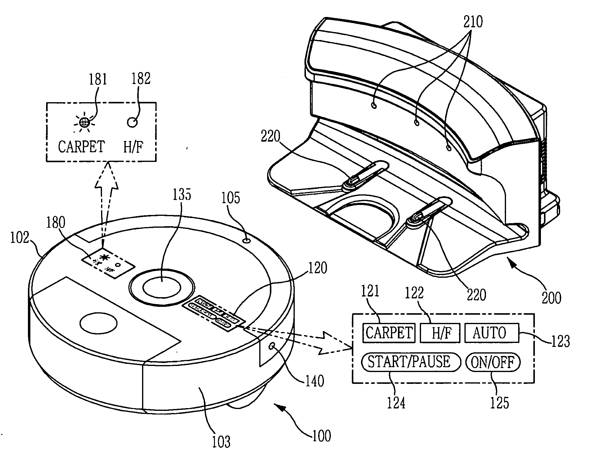
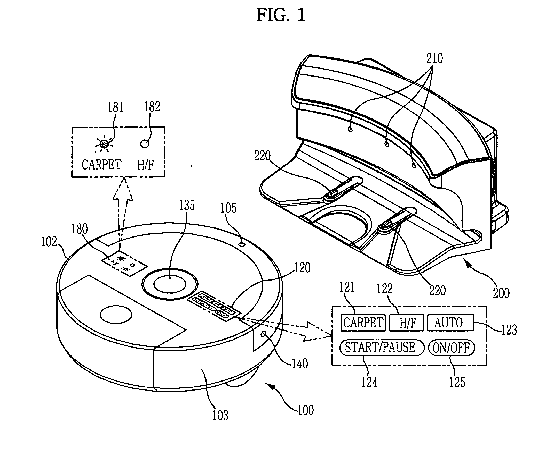
[0057]FIG. 1 is a perspective view illustrating external configurations of a robot cleaner and a docking station in accordance with an embodiment of the present disclosure.

[0058]As illustrated in FIG. 1, the robot cleaner 100 in accordance with the embodiment of the present disclosure includes a main body 102 forming the external appearance of the robot cleaner 100. The main body 102 is provided at a front upper position thereof with a receiver 105, which receives an infrared signal or ultrasonic signal generated from transmitters 210 of a docking station 200 when the robot cleaner 100 returns to the docking station 200.

[0059]In addition, an input unit 120 including a plurality of buttons to input a cleaning or docking operation command, an upward camera unit 135 to c...


PUM


Abstract

A robot cleaner includes a main brush to sweep or scatter dust off a floor, a main brush motor to rotate the main brush, a Revolution Per Minute (RPM) detector to detect an RPM of the main brush motor, and a control unit to determine a type of floor according to the RPM of the main brush motor acquired by the RPM detector and control an operation of the robot cleaner based on the determined type of floor. A carpet mode to clean only a carpet area and a hard floor mode to clean a hard floor area excluding the carpet area are given based on detected information relating to the material of a floor, which enables partial cleaning with respect to a cleaning area selected by a user and adjustment in the number of cleaning operations or the intensity of cleaning according to the material of the floor.

Description

CROSS-REFERENCE TO RELATED APPLICATIONS[0001]This application claims the benefit of Korean Patent Application No. 2010-0117332, filed on Nov. 24, 2010 in the Korean Intellectual Property Office, the disclosure of which is incorporated herein by reference.BACKGROUND[0002]1. Field[0003]Embodiments of the present disclosure relate to a robot cleaner to perform a cleaning operation according to the material or state of a floor and a control method thereof.[0004]2. Description of the Related Art[0005]In general, a robot cleaner automatically cleans an area to be cleaned by sucking up foreign substances, such as dust, from a floor while autonomously traveling about the area to be cleaned without user manipulation. During cleaning, the robot cleaner detects a distance from an object, such as furniture, office appliances and walls, present in the cleaning area using an infrared sensor, etc., to travel without collision with the obstacle based on detected information.[0006]Cleaning a given c...

Claims


Application Information

Patent Timeline
Patent Type & Authority Applications(United States)
IPC IPC(8): B08B1/04B08B7/00
CPCA47L9/28G05D2201/0203A47L9/2826A47L9/2831A47L9/2847A47L9/2852A47L9/2857A47L2201/02A47L2201/022A47L2201/04A47L2201/06G05D1/0227G05D1/0242G05D1/0246G05D1/0255G05D1/0274A47L9/2805
Inventor KIM, DONG WONLEE, JUN HWA
Owner SAMSUNG ELECTRONICS CO LTD
Why Eureka
Try Eureka