Solar cell module and solar photovoltaic system

a solar photovoltaic and solar cell technology, applied in the direction of basic electric elements, electrical equipment, semiconductor devices, etc., can solve the problem that the solar panels cannot be stacked when the solar panels are used, and achieve the effect of low cost, easy manufacturing, and high design freedom

Inactive Publication Date: 2012-05-24
SHARP KK
View PDF11 Cites 12 Cited by
  • Summary
  • Abstract
  • Description
  • Claims
  • Application Information

AI Technical Summary

Benefits of technology

[0017]The solar cell module of the present invention includes a light guide plate; at least one fluorescence-dispersed film in each of which a fluorescent substance is dispersed, the at least one fluorescence-dispersed film being adhered to respective at least one surface of the light guide plate; and a solar cell element which is provided on another surface of the light guide plate, the another surface being perpendicular to the at least one surface. The solar cell module, therefore, (i) has a high design freedom and (ii) can be easily manufactured at low cost.

Problems solved by technology

Therefore, such solar panels cannot be stacked when the solar panels are used.

Method used


Image

  • Solar cell module and solar photovoltaic system
  • Solar cell module and solar photovoltaic system
  • Solar cell module and solar photovoltaic system

Examples


embodiment 1

(Solar Cell Module 10)

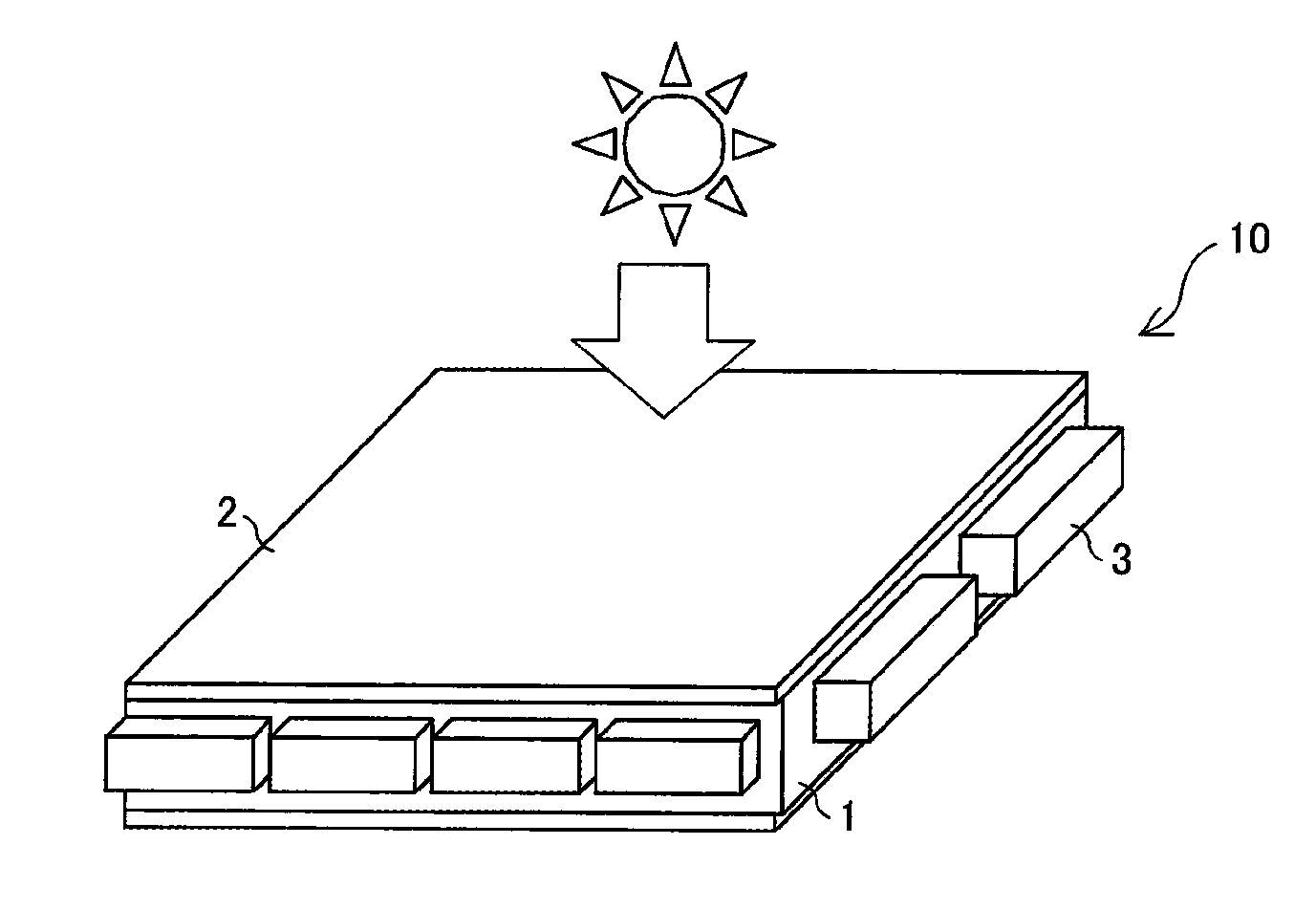
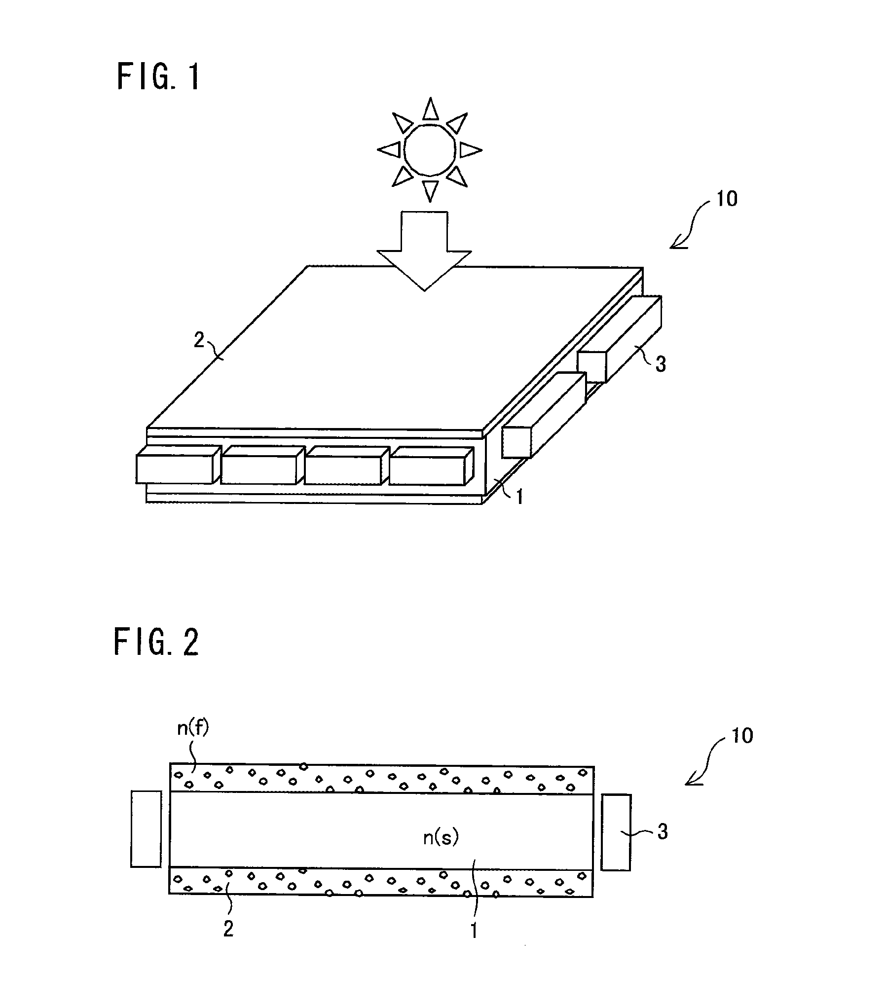
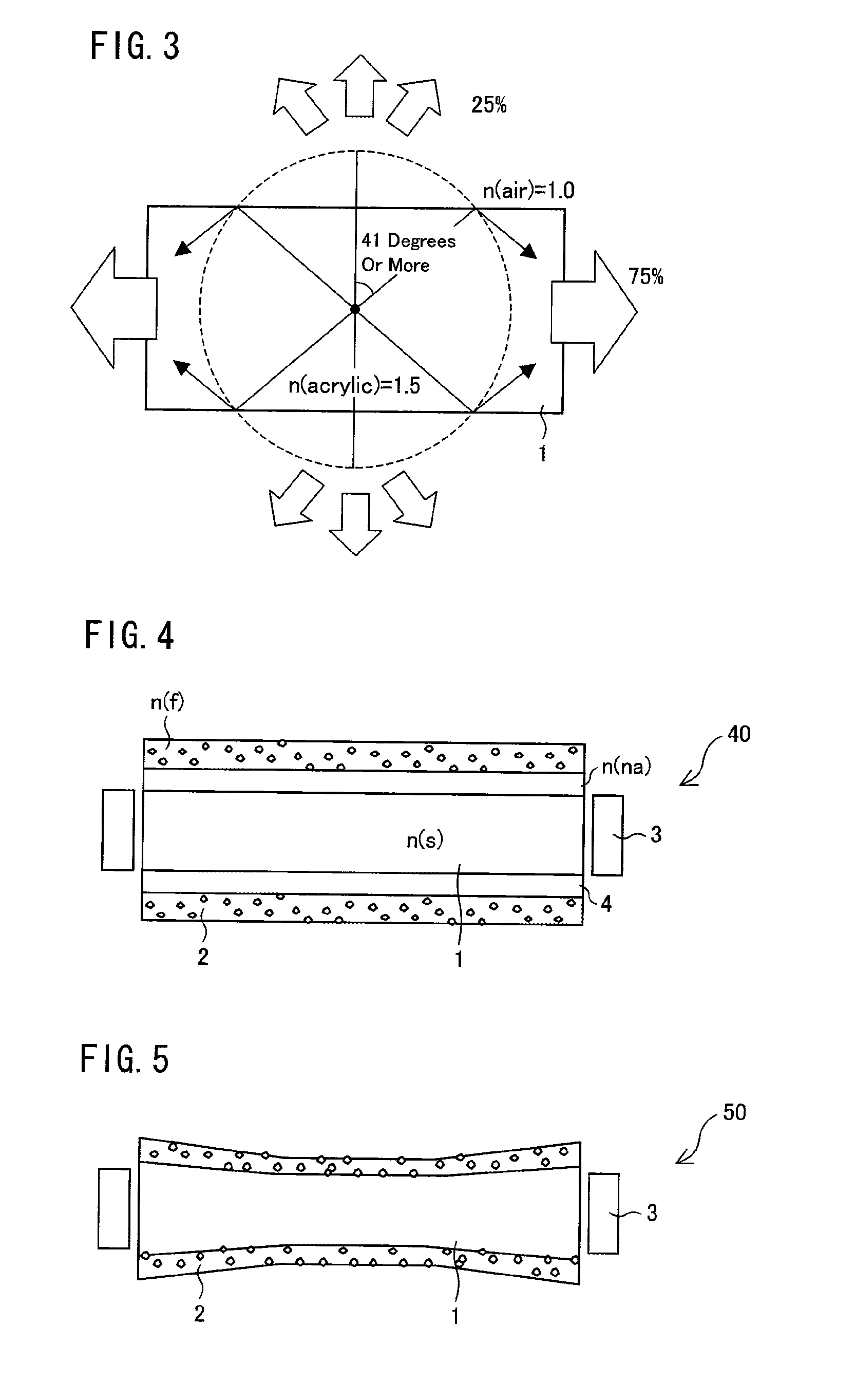
[0027]The following describes a solar cell module in accordance with an embodiment of the present invention, with reference to FIGS. 1 through 3. FIG. 1 is a perspective view illustrating a solar cell module 10. FIG. 2 is a cross-sectional view illustrating the solar cell module 10. FIG. 3 is a view for explaining how light is guided in the solar cell module 10.

[0028]The solar cell module 10 includes a light guide plate 1, a fluorescence-dispersed film 2, and solar cell elements 3 (see FIGS. 1 and 2). According to the light guide plate 1, the fluorescence-dispersed film 2 is adhered to an entire daylight surface which sunlight enters. According to the present embodiment, another fluorescence-dispersed film 2 is further adhered to another surface which faces the daylight surface. It follows that the light guide plate 1 is configured to be provided between the two fluorescence-dispersed films 2. Of course, a fluorescence-dispersed film 2 can be merely adhered to ...

embodiment 2

[0041]The following describes a solar cell module in accordance with another embodiment of the present invention, with reference to FIG. 4. A solar cell module 40 of this Embodiment 2 is different from the solar cell module 10 of Embodiment 1 in that the solar cell module 40 further includes an adhesive layer 4 which is provided between a light guide plate 1 and a fluorescence-dispersed film 2 so that the fluorescence-dispersed film 2 is adhered to the light guide plate 1 via the adhesive layer 4 (see FIG. 4). In this Embodiment 2, a description will be merely given to configurations different from those of Embodiment 1, and descriptions regarding the other configurations are omitted.

[0042]According to the solar cell module 40, the adhesive layer 4, the light guide plate 1, and the fluorescence-dispersed film 2 are configured so as to satisfy a relation n(f)≦n(a)≦n(s), where “n(a)” is a refractive index of the adhesive layer 4, “n(s)” is a refractive index of the light guide plate 1...

embodiment 3

[0045]A solar cell module of this Embodiment 3 is different from the solar cell module 40 of Embodiment 2 in that an infrared absorption agent is dispersed in a fluorescence-dispersed film 2. In this Embodiment 3, a description will be merely given to configurations different from those of Embodiment 2, and descriptions regarding the other configurations are omitted.

[0046]Aluminum nitride particles can be used as the infrared absorption agent which is to be dispersed in the fluorescence-dispersed film 2 of the solar cell module in accordance with the present embodiment. Note, however, that the infrared absorption agent is not limited to this. The infrared absorption agent, which is dispersed in the fluorescence-dispersed film 2, absorbs infrared light, which has a wavelength falling within a region Y of a solar energy distribution illustrated in a graph of FIG. 6, so as to prevent the infrared light from passing through the fluorescence-dispersed film 2.

[0047]It is preferable that t...


PUM


Abstract

The present invention provides a solar cell module which has high design freedom and can be easily manufactured at low cost. A solar cell module (10) includes (i) a light guide plate (1), (ii) a fluorescence-dispersed film (2) in each of which a fluorescent substance is dispersed and which is adhered to respective at least one surface of the light guide plate (1), and (iii) a solar cell element (3) which is provided on another surface of the light guide plate (1) which another surface being perpendicular to the at least one surface. Therefore, it is not necessary to prepare a light guide plate in which a fluorescent substance is dispersed. Moreover, it is possible to arbitrarily pattern the fluorescence-dispersed film (2) or to stack the fluorescence-dispersed films (2).

Description

TECHNICAL FIELD[0001]The present invention relates to a solar cell module and a solar photovoltaic device including the solar cell module.BACKGROUND ART[0002]According to a conventional solar photovoltaic device, which has been used so as to efficiently utilize solar energy, solar panels are generally spread all over a plane facing the sun. Such solar panels are each configured, in general, with the use of an opaque semiconductor. Therefore, such solar panels cannot be stacked when the solar panels are used. On this account, it is necessary to employ large solar panels in order to sufficiently collect sunlight, and accordingly, an installation area of the solar panels becomes larger. Patent Literature 1 discloses, as an example of such a solar photovoltaic device, a technique in which a fluorescent material film is provided on a light-receiving surface of a solar cell module so as to increase energy efficiency of incoming sunlight.[0003]Patent Literature 2 discloses a technique to e...

Claims


Application Information

Patent Timeline
Patent Type & Authority Applications(United States)
IPC IPC(8): H01L31/0232
CPCH01L31/02322H01L31/0547Y02E10/52H01L31/055H01L31/02327
Inventor MAEDA, TSUYOSHI
Owner SHARP KK
Why Eureka
Try Eureka