Hard Rock Rotary Drill Bit and Method of Drilling Using Crowned Cutter Elements

a cutter element and drill bit technology, applied in the field of drill bits, can solve problems such as easy chipping, and achieve the effects of preventing excessive wear, increasing the longitudinal movement of the drill string and the drill bit, and increasing the speed of rotation

Inactive Publication Date: 2012-05-24
TIGER 19 PARTNERS
View PDF1 Cites 28 Cited by
  • Summary
  • Abstract
  • Description
  • Claims
  • Application Information

AI Technical Summary

Benefits of technology

[0004]At the outer edge of the rotary drill bit, the peripherally spaced full-gauged PDC crowned elements are angled away from the longitudinal axis at about 30°. As each cutter element on a concentric ring scores the wellbore face, the hardened PDC composite crown of the first plurality of spaced elements wears down. Upon full wear of the crown of each primary PDC element, the second plurality of spaced PDC elements assumes the scuffing of the well bore in place of the first on each concentric ring. The outermost elements are placed at an angle of about 30° away from the longitudinal axis to continue scuffing the well bore face as well as to prevent excessive wear on the edge of the drill bit as drilling continues into the bore.
[0005]This disclosure also provides a method for rotary drilling of hard rock providing the steps of attaching a rotary bit having radially-spaced, longitudinally-aligned ballistic conical PDC crowned carbide elements arranged in a manner that permits only a single ballistic conical element to engage a borehole face at a radius from the central longitudinal axis of the drill bit; turning the rotary bit to engage the borehole face at a central location scouring a central groove in the borehole face; increasing the forward movement of the rotary drill bit to progressively advance the crowned carbide elements against the borehole face; and, clearing borehole cuttings from the face of the borehole utilizing the hydraulic pressure from a plurality of jetting nozzles in the face of the rotary bit. The velocity of the longitudinal movement of the drill string and bit can be increased after a desired borehole width is achieved, by increasing both the speed of rotation and increasing the weight on the bit, all in a manner well known in the drilling industry. Since each radial groove is being cut in the borehole face by a single cutter, the borehole face erodes quickly from both the deepening of the grooves formed by the PDC cutter elements and the collapse of the intervening peaks from one groove to the next outer groove.

Problems solved by technology

The PDC elements have long been known to withstand direct engagement with the well bore face but easily chip when minimally stressed on an angle to the cutter body.

Method used


Image

  • Hard Rock Rotary Drill Bit and Method of Drilling Using Crowned Cutter Elements
  • Hard Rock Rotary Drill Bit and Method of Drilling Using Crowned Cutter Elements
  • Hard Rock Rotary Drill Bit and Method of Drilling Using Crowned Cutter Elements

Examples


Embodiment Construction

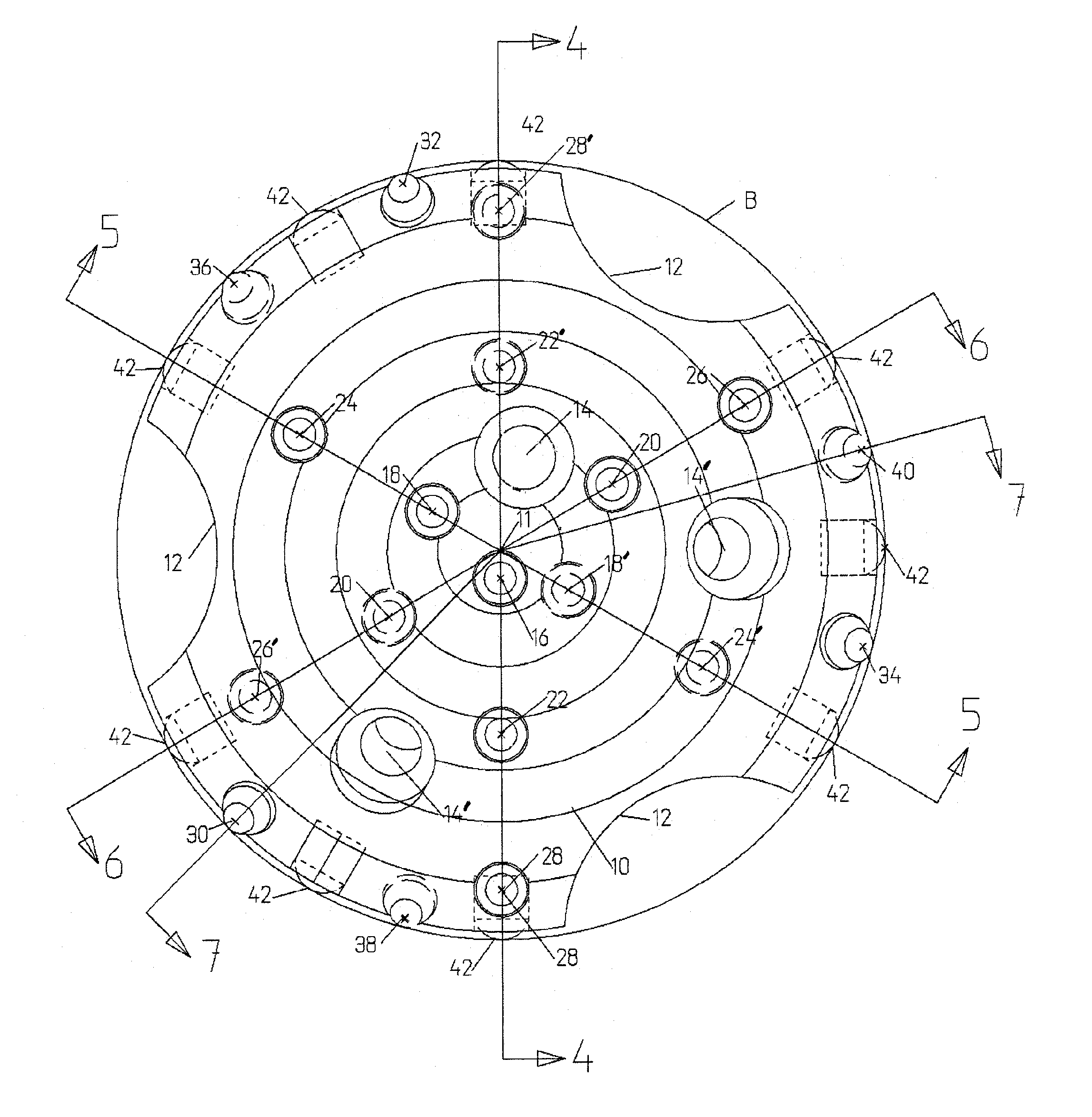
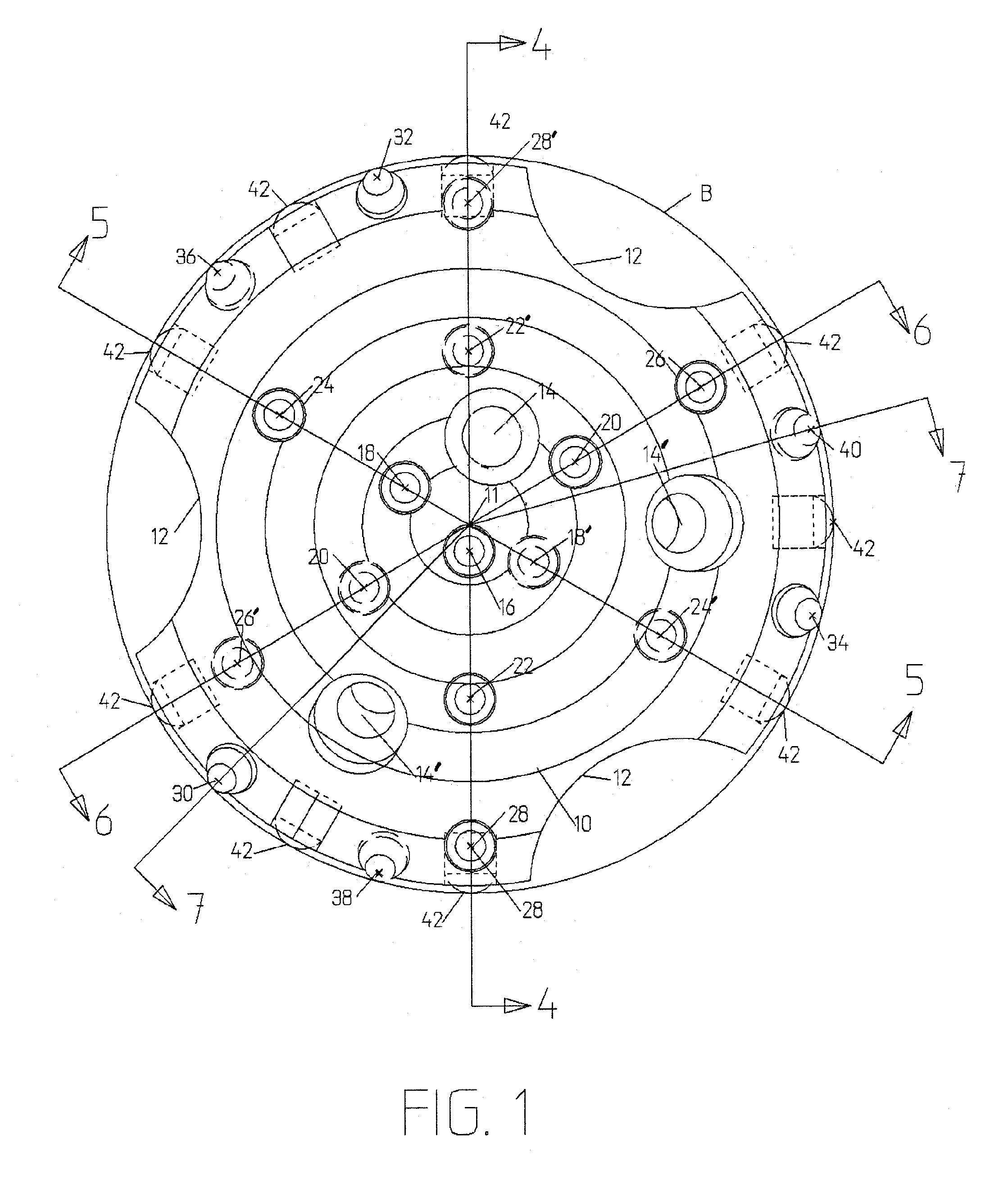
[0014]FIG. 1 is a detailed schematic layout of the drill bit face 10 of the present application showing the arrangement of the polycrystalline diamond compact cutters (PDC) of the present embodiment. Although applicant has described these as PDC elements, other hard faced cutter element inserts might be substituted, such as cubic boron nitride (PCBN), depending on the hardness of the rock being bored, without departing from the spirit or intent of this disclosure. Junk slots 12 and a plurality of jetting nozzle passages 14 and 14′ permit generous use of fluid to both cool the drill bit and flush cuttings away from the bore face.

[0015]The central cutter element 16 is affixed to the drill bit adjacent the central longitudinal axis 11 of the drill bit. Central cutter element 16 is the first to engage the face of the bore and scuffs and scores the face. Since the angle of incidence of the central cutter element 16 is virtually at 90° to the rock face, no or little chipping force is expe...


PUM


Abstract

This rotary drill bit provides a plurality of spaced polycrystalline diamond compact cutter elements arranged at spaced 120° concentric rings around the face of the drill bit and a secondary, redundant deeper set polycrystalline diamond compact cutter elements placed to commence scuffing the face of a bore upon wear of the primary cutter element, thereby providing extended continuous service in hard rock drill applications previously unattainable with conventional PDC bits.

Description

BACKGROUND OF INVENTION[0001]The present invention relates to a drill bit for use in drilling a bore in a hard-rock formation; and more specifically, to a rotary drill bit having a plurality of hardened cutting elements providing a polycrystalline diamond compact (PDC) crown coating on each spaced carbide insert button for scuffing a bore hole face and providing a secondary shadowing or redundant hardened PDC crowned cutting element to assume the scuffing action at the same radial groove created by the primary cutter element, after wear removes the PDC crown from the primary button. Button drill bits have long been known to be useable for drilling in formations for percussion-type bits. Some have suggested shaped button drill bits for rotary drill bit applications having cutting edges for cutting into the rock face. Others have provided enlarged buttons for crushing engagement of the well bore face. As an example, U.S. Pat. No. 4,109,731 discloses a drill bit having a plurality of P...

Claims


Application Information

Patent Timeline
Patent Type & Authority Applications(United States)
IPC IPC(8): E21B7/00E21B10/36
CPCE21B10/43E21B10/36
Inventor RIVES, ALLEN KENT
Owner TIGER 19 PARTNERS
Why Eureka
Try Eureka