Manufacturing method for a glass film

a manufacturing method and glass film technology, applied in the direction of manufacturing tools, metal-working equipment, thin material processing, etc., can solve the problems of unnecessarily expanding the manufacturing line, affecting the quality of the product glass portion (glass product),

Active Publication Date: 2012-05-24
NIPPON ELECTRIC GLASS CO LTD
View PDF26 Cites 23 Cited by
  • Summary
  • Abstract
  • Description
  • Claims
  • Application Information

AI Technical Summary

Benefits of technology

[0024]As described above, according to the present invention, it is possible to obtain a high-quality product glass portion from a band-like glass film without unnecessarily upsizing a manufacturing line therefor.

Problems solved by technology

Further, during the period in which the unnecessary glass portion is being broken, there may occur, in many cases, such vibrations that the continuously delivered unnecessary glass portion vibrates mainly in a thickness direction thereof.
As a result, the cleaving accuracy of the glass film and, by extension, the quality of the product glass portion (glass product) may be affected adversely.
However, there arises such a new problem that a manufacturing line is unnecessarily upsized.

Method used


Image

  • Manufacturing method for a glass film
  • Manufacturing method for a glass film
  • Manufacturing method for a glass film

Examples


Embodiment Construction

[0035]Hereinafter, an embodiment of the present invention is described with reference to the drawings.

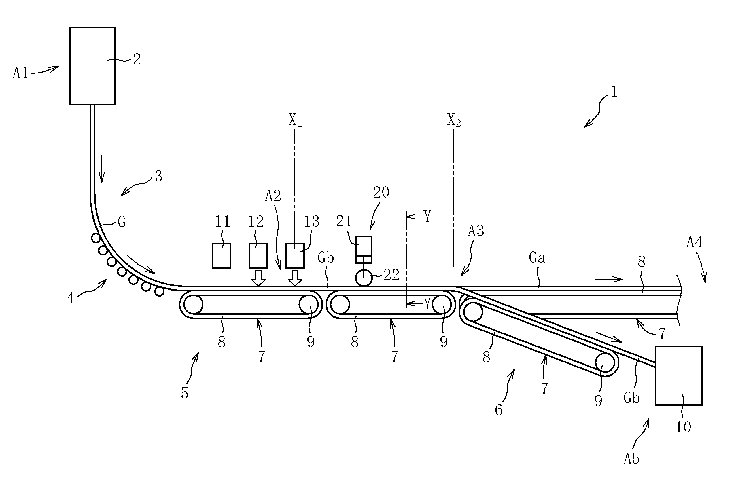
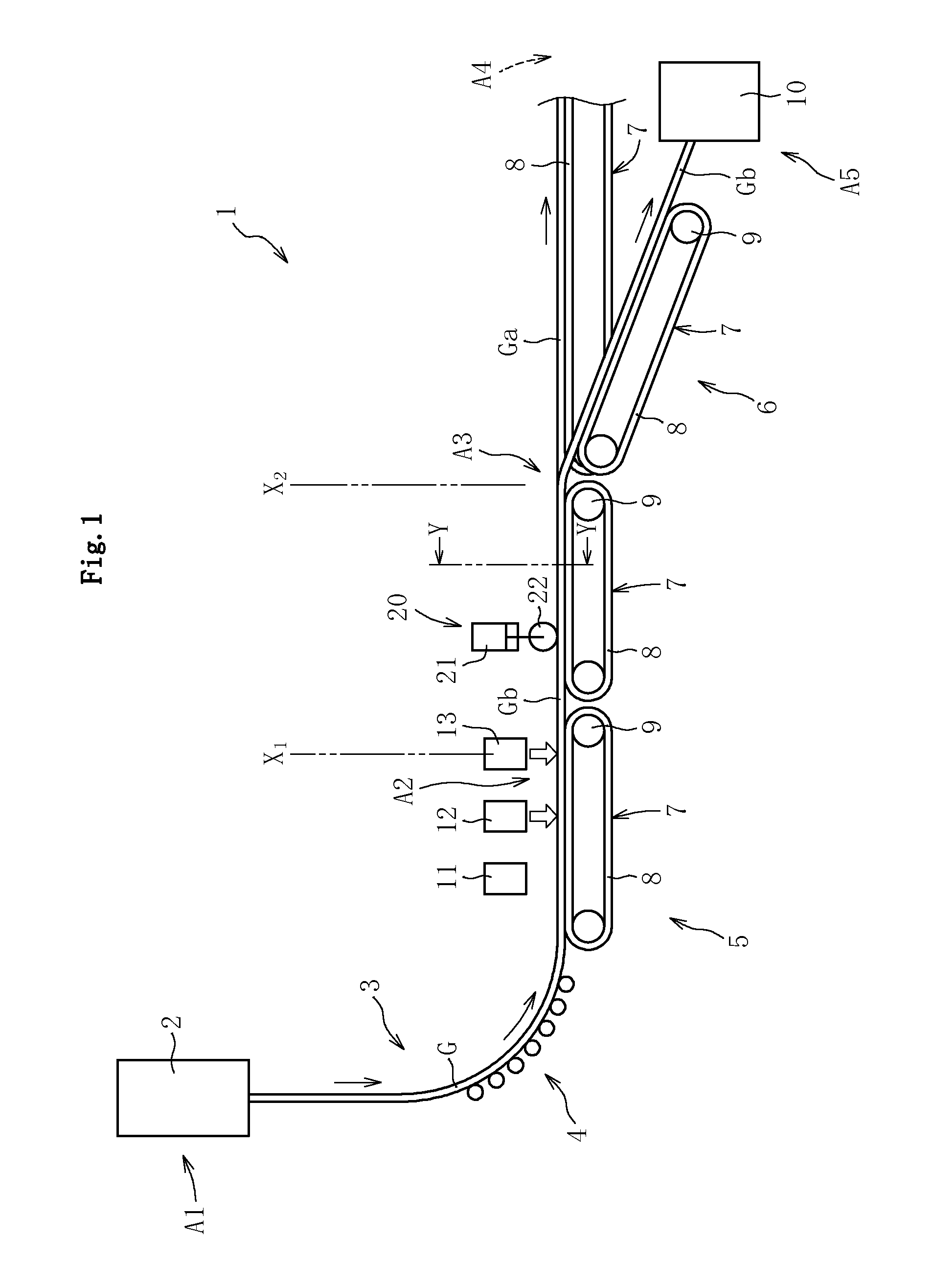
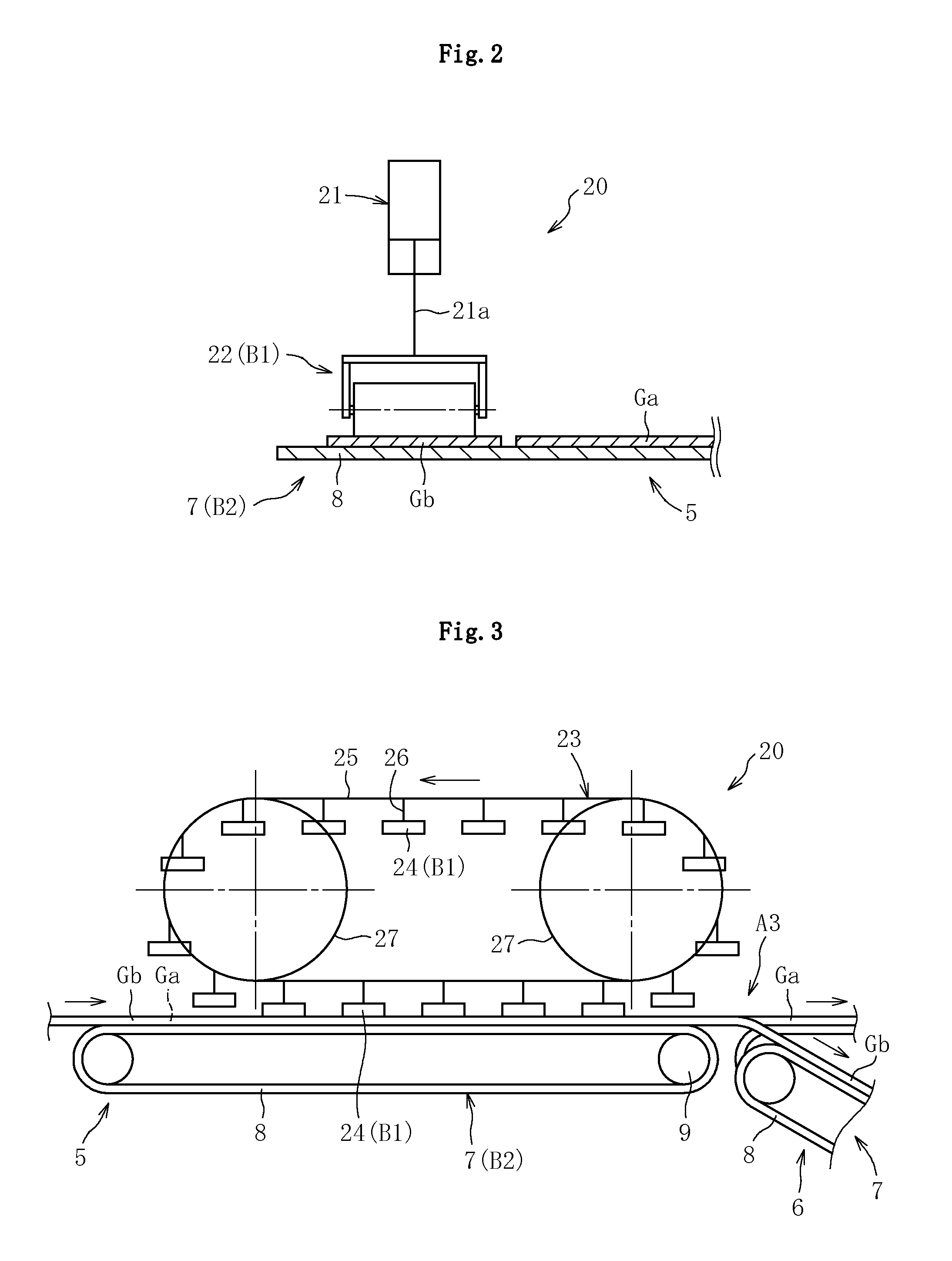
[0036]FIG. 1 is a schematic side view illustrating an example of a manufacturing line (manufacturing apparatus) 1 to be used for implementing a manufacturing method for a glass film according to the present invention. The manufacturing line 1 mainly includes, in combination, a forming area A1, a cleaving area A2, a separating area A3, a finishing area A4, and a collecting area A5 which are described below in detail.

[0037]The forming area A1 is a forming step area for forming a long (band-like) glass film G having a longitudinal dimension exceeding 4 m, and a forming device 2 is provided in the forming area A1. As the forming device 2, there is herein used a forming device for forming the glass film G by a so-called overflow downdraw method, in which molten glass is successively drawn downward vertically. In the overflow downdraw method, the forming of the glass film G proceeds under...


PUM

PropertyMeasurementUnit
thicknessaaaaaaaaaa
thicknessaaaaaaaaaa
thicknessaaaaaaaaaa

Abstract

The manufacturing method for a glass film includes, in this order: a cleaving step of dividing a glass film (G) having a band shape into a product glass portion (Ga) and an unnecessary glass portion (Gb); and a collecting step of sequentially shattering the unnecessary glass portion (Gb), and collecting the shattered unnecessary glass portion. The cleaving step is followed by vibration regulating processing of regulating vibrations of the unnecessary glass portion (Gb) in a thickness direction thereof, the vibration regulating processing being executed in at least one location in the longitudinal direction of the unnecessary glass portion (Gb) together with the collecting step executed on a downstream side of the at least one location of the vibration regulating processing.

Description

BACKGROUND OF THE INVENTION[0001]1. Field of the Invention[0002]The present invention relates to an improvement of a manufacturing method for a glass film.[0003]2. Description of Related Art[0004]As is well known, flat panel displays (FPDs) have become mainstream as image display devices in recent years, the FPDs being typified by a liquid crystal display (LCD), a plasma display (PDP), an OLED display (OLED), and the like. Progress is being made toward further reducing the weight of those FPDs, and hence there is promoted further thinning of glass sheets used as a main component for the FPDs.[0005]Further, for example, there is a growing use of an organic light-emitting diode not only for applications to a display that uses TFTs to blink light of three primary colors, but also as a plane light source, such as a backlight of the LCD and a light source for interior illumination, which emits only monochrome light. An illumination device that uses the organic light-emitting diode as a l...

Claims


Application Information

Patent Timeline
Patent Type & Authority Applications(United States)
IPC IPC(8): C03B33/09
CPCC03B33/0235C03B33/091C03B33/033Y02P40/57Y10T225/14
Inventor FURUTA, TAKAYANISHIJIMA, KOJIMORI, KOICHIMATSUMOTO, YASUHIRONAKABAYASHI, AKIO
Owner NIPPON ELECTRIC GLASS CO LTD
Why Eureka
Try Eureka