Organic electroluminescent element
a technology of electroluminescent elements and organic materials, which is applied in the direction of organic semiconductor devices, thermoelectric devices, solid-state devices, etc., can solve the problems of hammering the practical use of devices, and achieve the effect of simple manufacturing process, high efficiency and long-life organi
- Summary
- Abstract
- Description
- Claims
- Application Information
AI Technical Summary
Benefits of technology
Problems solved by technology
Method used
Image

Examples
first exemplary embodiment
Arrangement of Organic EL Device
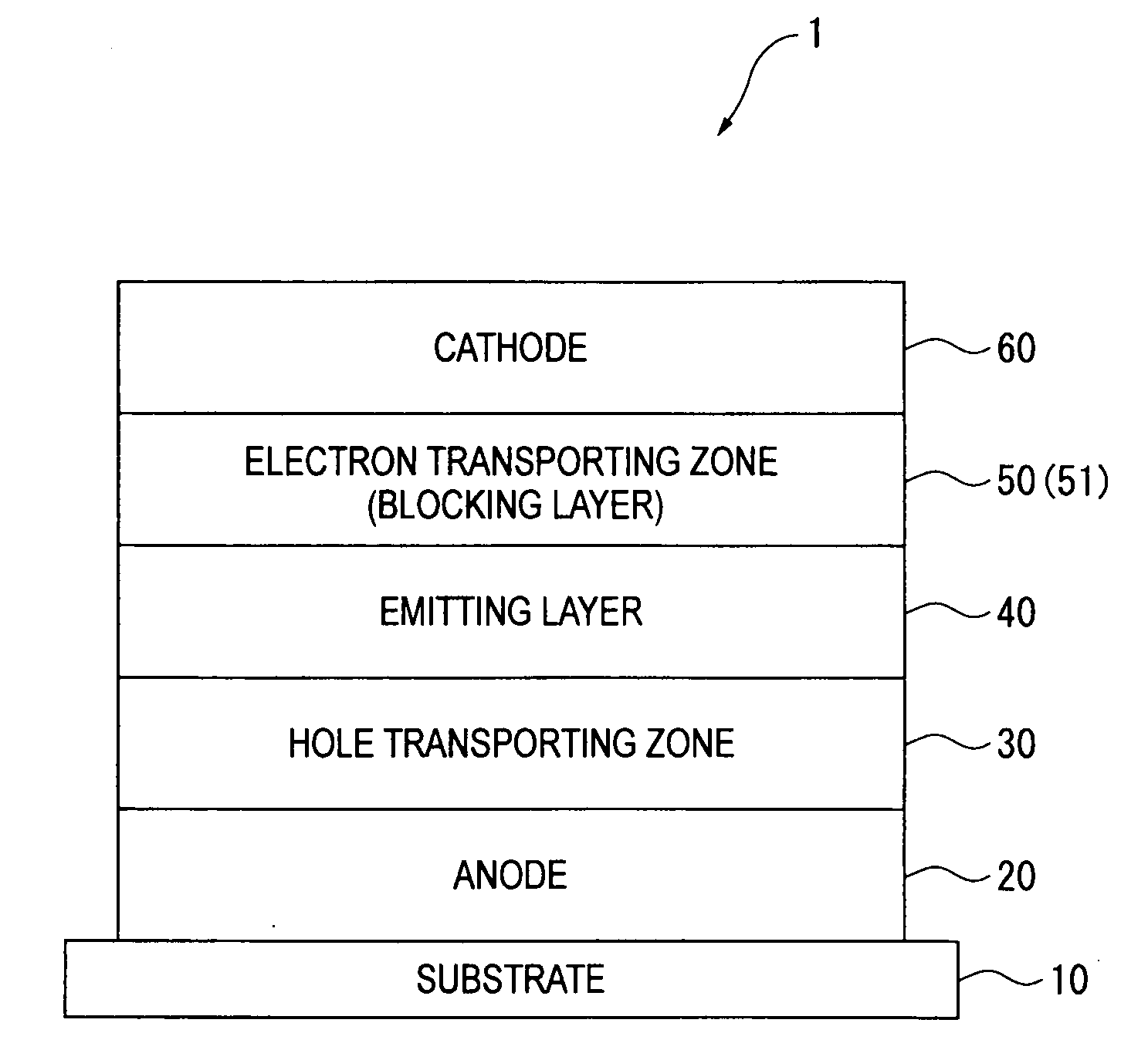
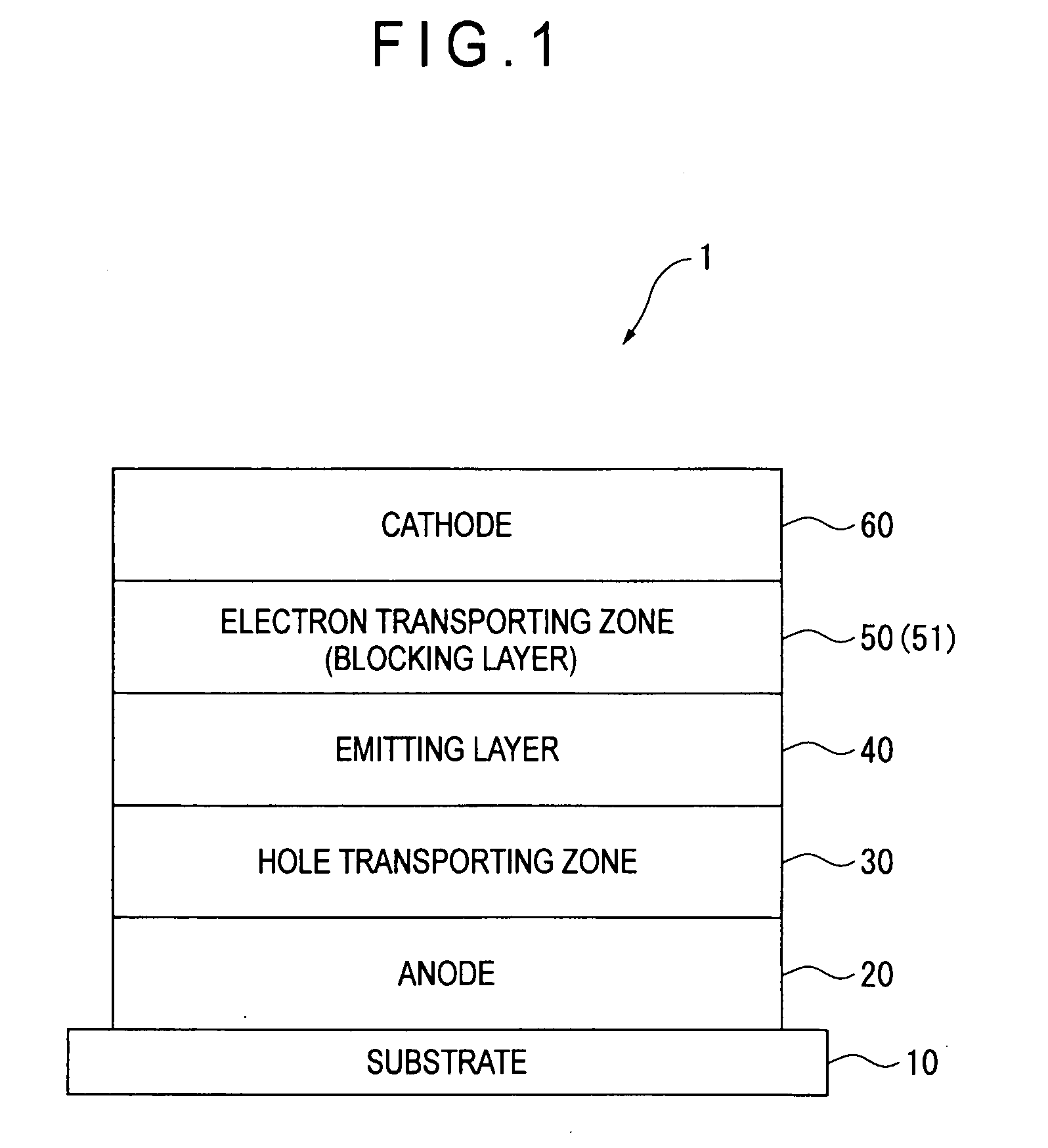
[0049]In an organic EL device 1 shown in FIG. 1, an anode 20, a hole transporting zone 30, an emitting layer 40, an electron transporting zone 50 and a cathode 60 are laminated on a substrate 10 in sequential order.
Electron Transporting Zone / Blocking Layer
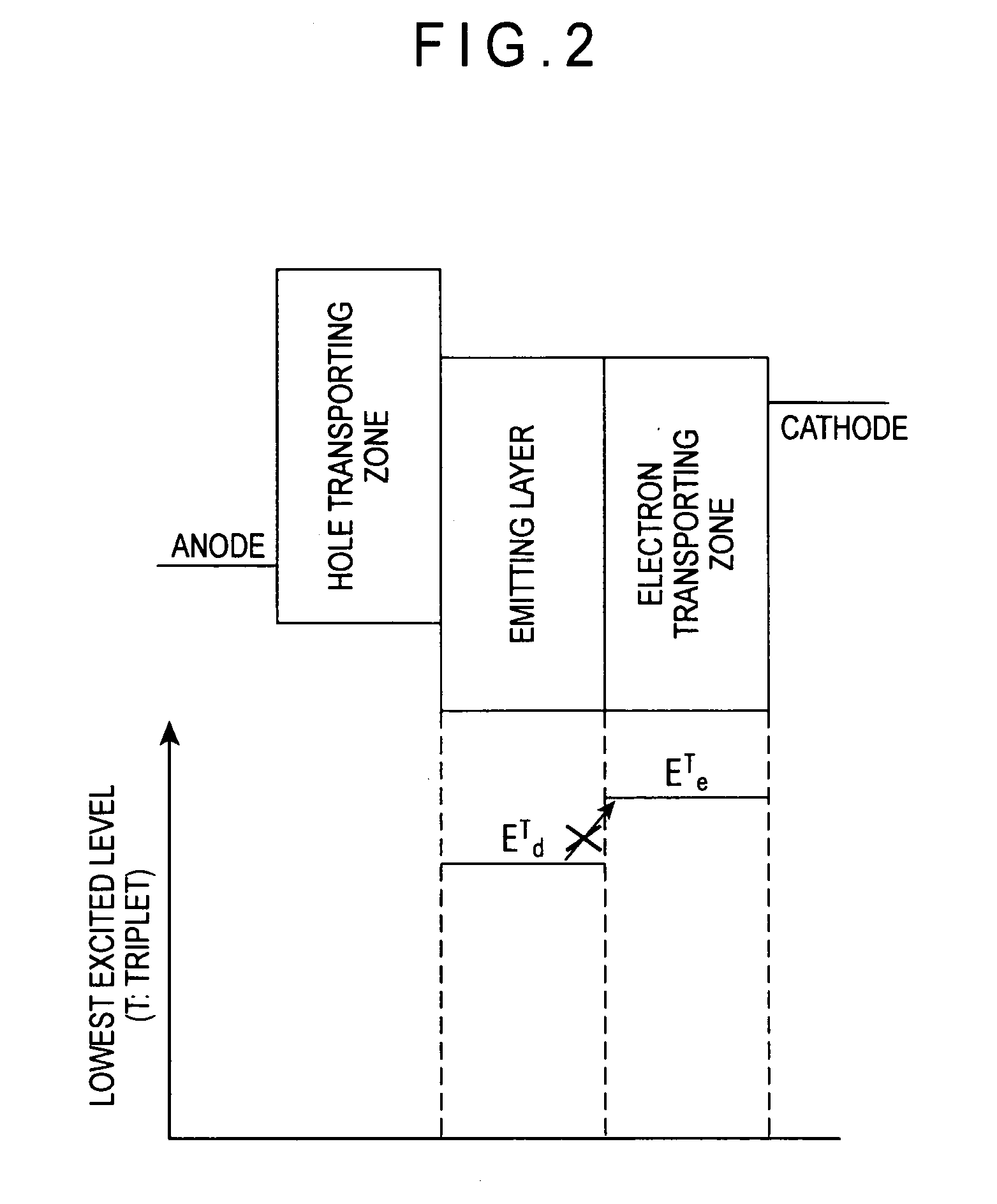
[0050]A blocking layer 51 is provided adjacently to the emitting layer40 in the electron transporting zone 50. The blocking layer 51 has a function to prevent triplet excitons generated in the emitting layer 40 from energy-transferring into the electron transporting zone 50 and to trap the triplet excitons in the emitting layer 40, thereby increasing a density of the triplet excitons in the emitting layer 40 (described later).
[0051]The blocking layer 51 includes: a fused hydrocarbon compound; and at least one compound selected from an electron-donating dopant and an organic metal complex containing an alkali metal. The blocking layer 51 preferably includes at the mass ratio in a range of 30:70 to 70:...
second exemplary embodiment
[0121]Next, a second exemplary embodiment of the invention will be described.
[0122]In the description of the second exemplary embodiment, the same components as those in the first exemplary embodiment will be denoted by the same reference numerals to simplify or omit description of the components. The fused hydrocarbon compound, the electron-donating dopant, the organic metal complex including an alkali metal and other compounds used in the second exemplary embodiment are the same compounds described in the first exemplary embodiment.
[0123]In an organic EL device 2 according to the second exemplary embodiment, as shown in FIG. 3, a layer (an electron injecting layer) 52 is formed in the electron transporting zone 50 and between the blocking layer 51 and the cathode 60, the layer 52 being formed by at least one compound selected from the electron-donating dopant and the organic metal complex including an alkali metal. The electron injecting layer 52 does not contain the fused hydroca...
third exemplary embodiment
[0131]Next, a third exemplary embodiment of the invention will be described.
[0132]In the description of the third exemplary embodiment, the same components as those in the first exemplary embodiment are denoted by the same reference numerals to simplify or omit description of the components. The fused hydrocarbon compound, the electron-donating dopant, the organic metal complex including an alkali metal and other compounds used in the third exemplary embodiment are the same compounds described in the first exemplary embodiment.
[0133]An organic EL device 3 according to the third exemplary embodiment, as shown in FIG. 4, is provided with the blocking layer 51 in the electron transporting zone 50 in the same manner as in the first exemplary embodiment and includes a first organic thin-film layer 53 and a second organic thin-film layer 54 which are sequentially laminated on the emitting layer 40.
[0134]The first organic thin-film layer 53 is formed of the fused hydrocarbon compound and i...
PUM
 Abstract
Description
Claims
Application Information
 - R&D
- Intellectual Property
- Life Sciences
- Materials
- Tech Scout
- Unparalleled Data Quality
- Higher Quality Content
- 60% Fewer Hallucinations
Browse by: Latest US Patents, China's latest patents, Technical Efficacy Thesaurus, Application Domain, Technology Topic, Popular Technical Reports.
© 2025 PatSnap. All rights reserved.Legal|Privacy policy|Modern Slavery Act Transparency Statement|Sitemap|About US| Contact US: help@patsnap.com