On-board wireless communication apparatus and on-board wireless communication system

a wireless communication and wireless communication technology, applied in the field of on-board wireless communication apparatus and on-board wireless communication system, can solve the problems of reducing system throughput, overhead due to increase in the number of packet transmissions, and exhausted stored data in the reception buffer, so as to improve system throughput and reduce the capacity of the reception buffer to be prepared

Inactive Publication Date: 2012-05-24
MITSUBISHI ELECTRIC CORP
View PDF4 Cites 47 Cited by
  • Summary
  • Abstract
  • Description
  • Claims
  • Application Information

AI Technical Summary

Benefits of technology

[0008]According to the on-board wireless communication apparatus according to the invention, since the on-board wireless communication apparatus is configured such that the request for the appropriate transmission rate and bandwidth is notified to the base station, the minimum band for each data type can be secured to enhance the system throughput. In addition, since the data storage amount in the reception buffer unit can be stably retained, the capacity of the reception buffer to be prepared can be reduced.

Problems solved by technology

In the portable communication terminal apparatus disclosed in Patent Document 1, since the packet length is shortened even in such a situation, an overhead due to an increase in the number of times of the packet transmission is increased; consequently, there is a problem such that the system throughput is lowered.
In addition, in the portable communication terminal apparatus disclosed in Patent Document 1, since a data reception request on the reception side is not taken into consideration, the transmission is not performed even when data transmission can be performed without an error by allocating a robust and low transmission rate to the transmission path, and thus, there are cases where stored data in a reception buffer is exhausted.

Method used


Image

  • On-board wireless communication apparatus and on-board wireless communication system
  • On-board wireless communication apparatus and on-board wireless communication system
  • On-board wireless communication apparatus and on-board wireless communication system

Examples


embodiment 1

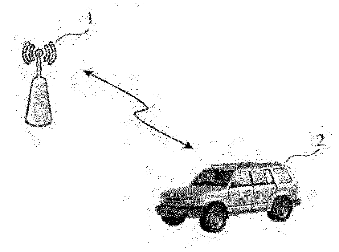
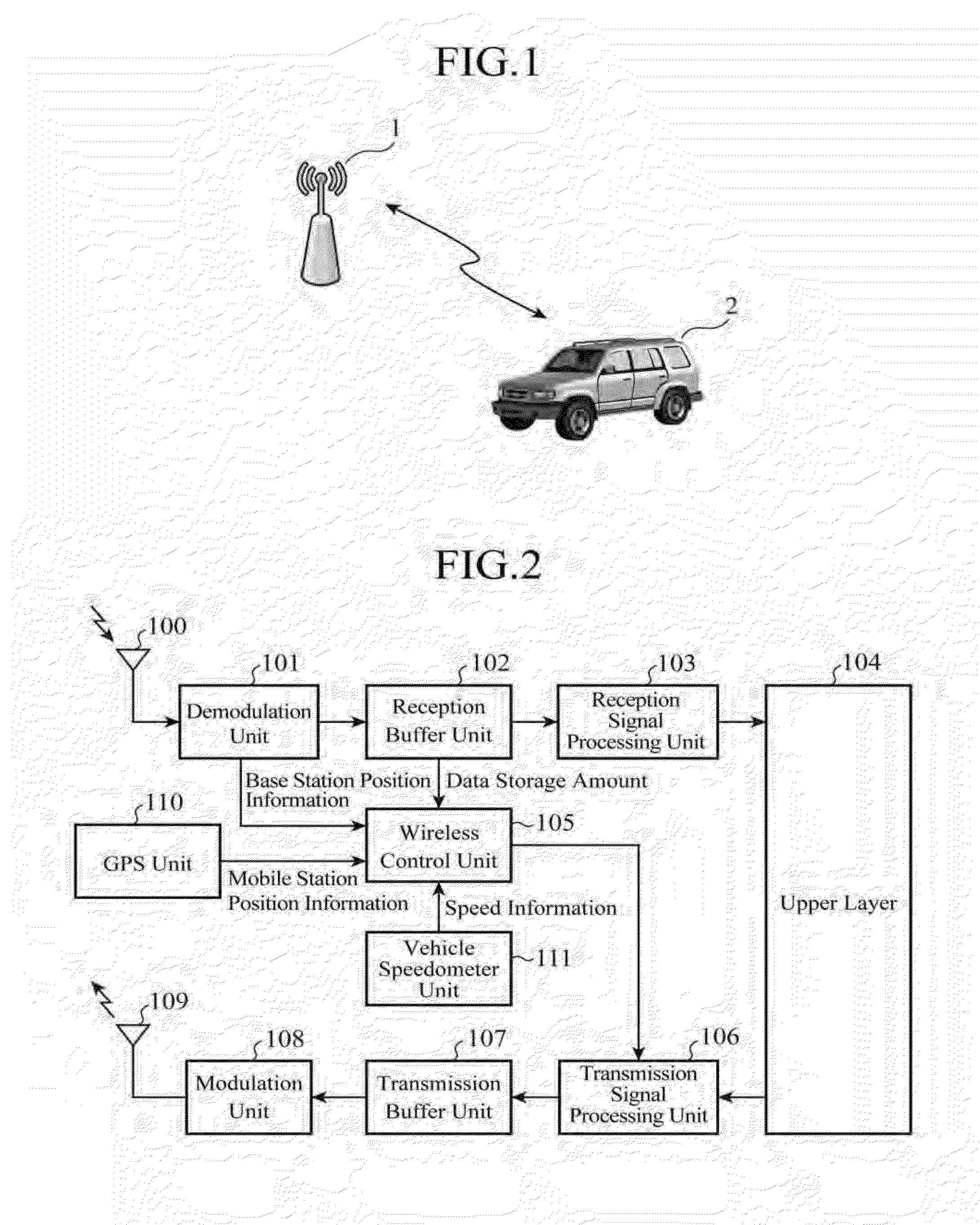
[0022]FIG. 1 is a view showing a configuration of an on-board wireless communication system using an on-board wireless communication apparatus of Embodiment 1 in the invention. The on-board wireless communication system has a base station (BS) 1 and a mobile station (MS) 2 including the on-board wireless communication apparatus, and wireless communication using an OFDMA (Orthogonal Frequency Division Multiple Access) scheme is performed between the two stations. The OFDMA scheme is a multiplexing one in which a sub-channel composed of the combination of a logic channel of a frequency axis resulting from division of a sub-carrier and a time slot is allocated to each user.

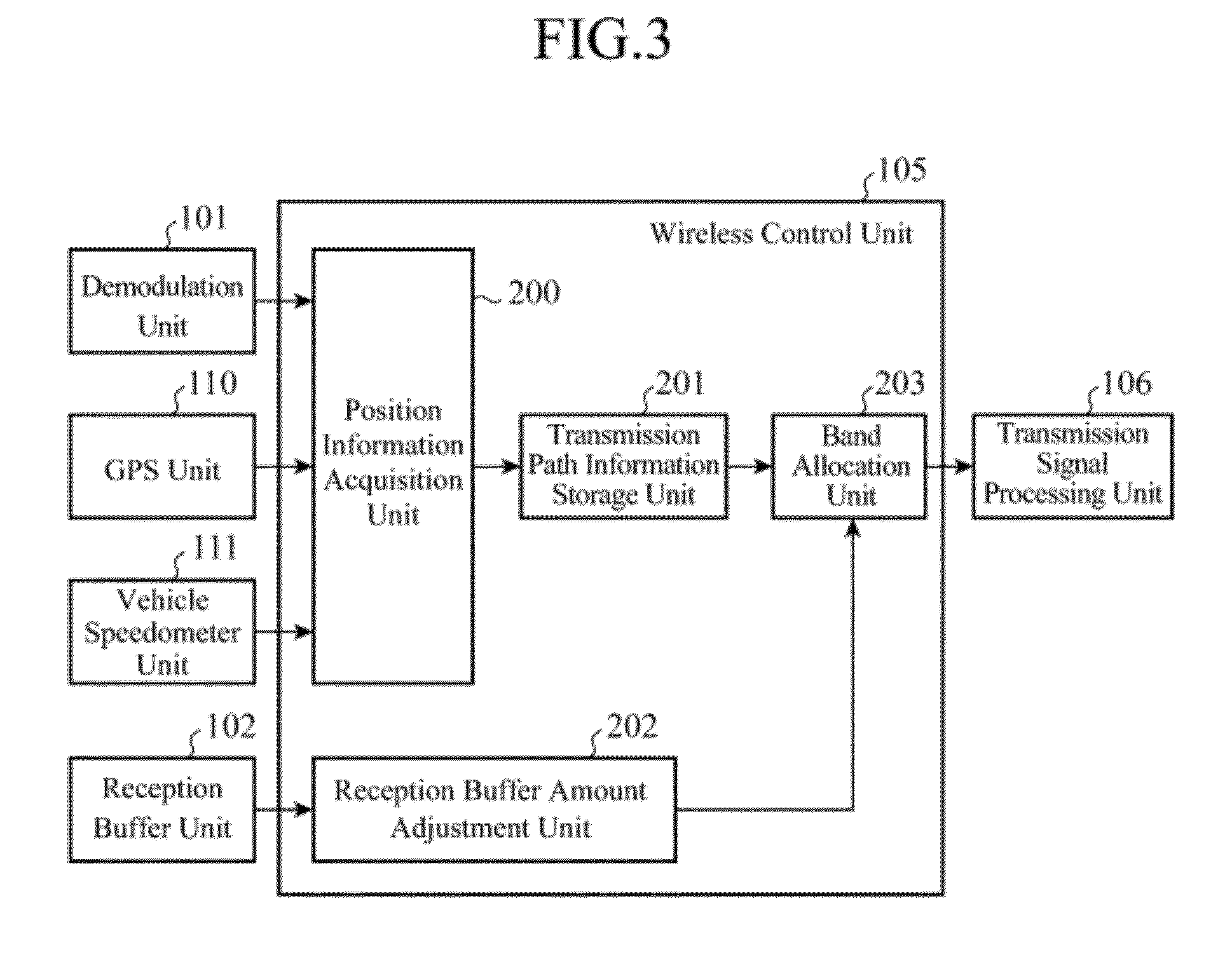
[0023]FIG. 2 is a block diagram showing the whole configuration of the mobile station 2. The mobile station 2 is constructed as, for example, a part of a navigation apparatus for implementing navigation functions, and includes a reception antenna 100, a demodulation unit 101, a reception buffer unit 102, a reception ...

embodiment 2

[0047]In the acquisition of the position information upon reception of the next frame by the position information acquisition unit 200 of the on-board wireless communication apparatus of Embodiment 1 discussed above, an on-board wireless communication apparatus of Embodiment 2 in the invention is configured such that the position estimation is performed by an addition of route setting information obtained by the use of a route search function of the navigation functions.

[0048]FIG. 11 is a block diagram showing a detailed configuration of the wireless control unit 105 of the on-board wireless communication apparatus of Embodiment 2. The on-board wireless communication apparatus is configured by adding a vehicle information input unit 113 to the on-board wireless communication apparatus of Embodiment 1. The vehicle information input unit 113 inputs the route setting information indicating a driving route to a destination which is calculated by the use of the route search function of t...

embodiment 3

[0052]In the acquisition of the position information upon reception of the next frame by the position information acquisition unit 200 of the on-board wireless communication apparatus of Embodiment 1 discussed above, an on-board wireless communication apparatus of Embodiment 3 in the invention is configured such that the position estimation is performed by a further addition of traffic jam information acquired from VICS (Vehicle Information and Communication System: registered trademark, hereinafter omitted).

[0053]The configuration of the on-board wireless communication apparatus of Embodiment 3 is the same as that of the on-board wireless communication apparatus of Embodiment 2 shown in FIG. 11 except that the vehicle information input unit 113 inputs VICS information to be sent to the position information acquisition unit 200. In this case, the position information acquisition unit 200 estimates the position of the mobile station 2 upon reception of the next frame on the basis of ...


PUM


Abstract

An on-board wireless communication apparatus using an OFDMA scheme includes: a position information acquisition unit which estimates a position after a predetermined time period based on base station position information, mobile station position information, and speed information of mobile station as estimated mobile station position information; a transmission path information storage unit which determines a transmission rate to be applied based on the estimated position information and a distribution of the transmission rate determined by a distance from the base station; a reception buffer unit which stores received data; a reception buffer amount adjustment unit which determines a data amount to be received based on a data storage amount from the buffer unit and a type of the data therein; and a band allocation unit which determines a band requested to the base station by the transmission rate from the storage unit and the data amount from the adjustment unit.

Description

TECHNICAL FIELD[0001]The present invention relates to an on-board wireless communication apparatus which is mounted on, for example, a vehicle to perform wireless communication with the outside, and an on-board wireless communication system.BACKGROUND ART[0002]The state of a transmission path in wireless communication performed in an on-board wireless communication apparatus momentarily fluctuates, and the fluctuation becomes further noticeable as the on-board wireless communication apparatus moves. Patent Document 1 discloses a portable communication terminal apparatus capable of reducing power consumption while reducing the consumption of a communication resource even when the state of the transmission path is unstable. In the portable communication terminal apparatus, as an acceleration or moving speed thereof is increased, a packet error rate is increased, so that the packet error becomes likely to occur, and thus an object of the apparatus is to avoid the packet error by changi...

Claims


Application Information

Patent Timeline
Patent Type & Authority Applications(United States)
IPC IPC(8): H04W72/04H04L47/30H04W4/02
CPCH04W4/02H04W64/006H04W28/18H04W40/20H04W72/0413H04W72/21H04W72/51
Inventor USUI, TSUTOMU
Owner MITSUBISHI ELECTRIC CORP
Why Eureka
Try Eureka