Conveyor chain for a radiographic inspection system and radiographic inspection system

a radiographic inspection system and conveyor chain technology, applied in the direction of conveyors, measuring devices, instruments, etc., can solve the problems of conveyor chains unsuitable for radiographic inspection systems, easy damage and rapid wear, and the use of customary chain conveyors with plastic chain links is problematic in radiographic inspection systems

Inactive Publication Date: 2012-05-24
METTLER TOLEDO SAFELINE X RAY
View PDF7 Cites 15 Cited by
  • Summary
  • Abstract
  • Description
  • Claims
  • Application Information

AI Technical Summary

Benefits of technology

[0005]To the extent that conveyor belts are used as transport devices in radiographic inspection systems, they are in most cases fabric polymer belts. This type of conveyor has the feature that the quality of the X-ray image is least affected by it, due to the constant thickness and the uniformity of the belt. However, there is strong resistance to the use of fabric belts in the bottling and canning industry, because they are easily damaged and wear out rapidly. In comparison, conveyor chains consisting of rigid plastic elements (typically of acetal resin or polypropylene) that are linked together in an endless loop are much stronger and less easily damaged by hard metal or glass containers. Conveyor chains are also easier to replace or repair than belts, because the chain can be opened by removing the hinge pins by which the modular elements of the chain are linked together. Finally, conveyor chains can be designed to be self-tracking and to run flush with the side of the conveyor structure. This last characteristic is important, because it allows products to be easily transferred sideways between laterally adjacent conveyors.
[0008]U.S. Pat. No. 1,136,578 shows a conveyor that is composed of links hinged to each other. A conveyor floor is achieved by mounting a strip in a central portion thereof to a plate-like portion provided on each of the links. The strips form a flat surface and comprise down-turned flanges with beveled corners in the direction of movement, the function of which is to stabilize the strips.
[0009]In light of the shortcomings of the known art, an exemplary embodiment of a conveyor for a radiographic inspection system may combine the advantages of uniform thickness and density of a fabric-backed polymer belt with the stability and wear-resistance of a chain of articulately connected rigid elements. An exemplary embodiment may also provide a radiographic inspection system that includes this example of a conveyor as a component.
[0011]This continuous, materially homogenous transport area of uniform thickness and density is a central aspect of an exemplary embodiment, as it may ensure that the part of the conveyor which supports the articles under inspection has a uniform transmissivity for the scanning radiation. This means that an exemplary embodiment of the conveyor comprises in its transport area a homogenous radiographic cross section, i.e., a cross section with insignificant loss of transmitted electromagnetic radiation intensity at any boundary surfaces when passing the conveyor chain.
[0013]In an exemplary embodiment, the connector elements, in particular the hinges, are preferably arranged on the underside, i.e., the inside surface of the conveyor chain loop, so that the outward-facing surface or transport surface of the conveyor chain loop is flat and unobstructed, which facilitates, for example, the sideways transfer of objects from one conveyor chain to another.
[0018]Advantageously, the curtain of scanning radiation in an exemplary embodiment may extend in a plane that is inclined at an oblique angle to the transport surface and intersect the latter along a line that runs perpendicular to the transport direction. For the obliquely directed radiation, the segments may therefore effectively present an overlap at the joints, so that there is substantially no change in transmissivity when a joint passes through the inclined curtain of radiation.

Problems solved by technology

Furthermore, if the container has a domed bottom, the foreign bodies will tend to settle at the perimeter where the bottom meets the sidewall of the container.
However, there is strong resistance to the use of fabric belts in the bottling and canning industry, because they are easily damaged and wear out rapidly.
On the other hand, as mentioned in U.S. Pat. No. 7,106,827 B2, the use of customary chain conveyors with plastic chain links is problematic in radiographic inspection systems, because the chain links can interfere with the X-ray image.
In the foregoing examples of the existing known art, the metallic parts alone would make these conveyor chains unsuitable for a radiographic inspection system.

Method used


Image

  • Conveyor chain for a radiographic inspection system and radiographic inspection system
  • Conveyor chain for a radiographic inspection system and radiographic inspection system
  • Conveyor chain for a radiographic inspection system and radiographic inspection system

Examples


Embodiment Construction

)

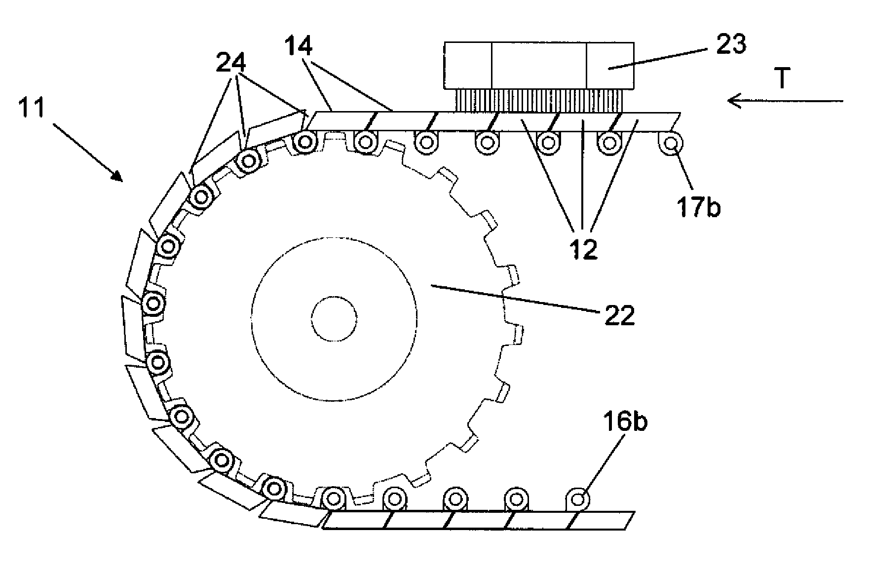
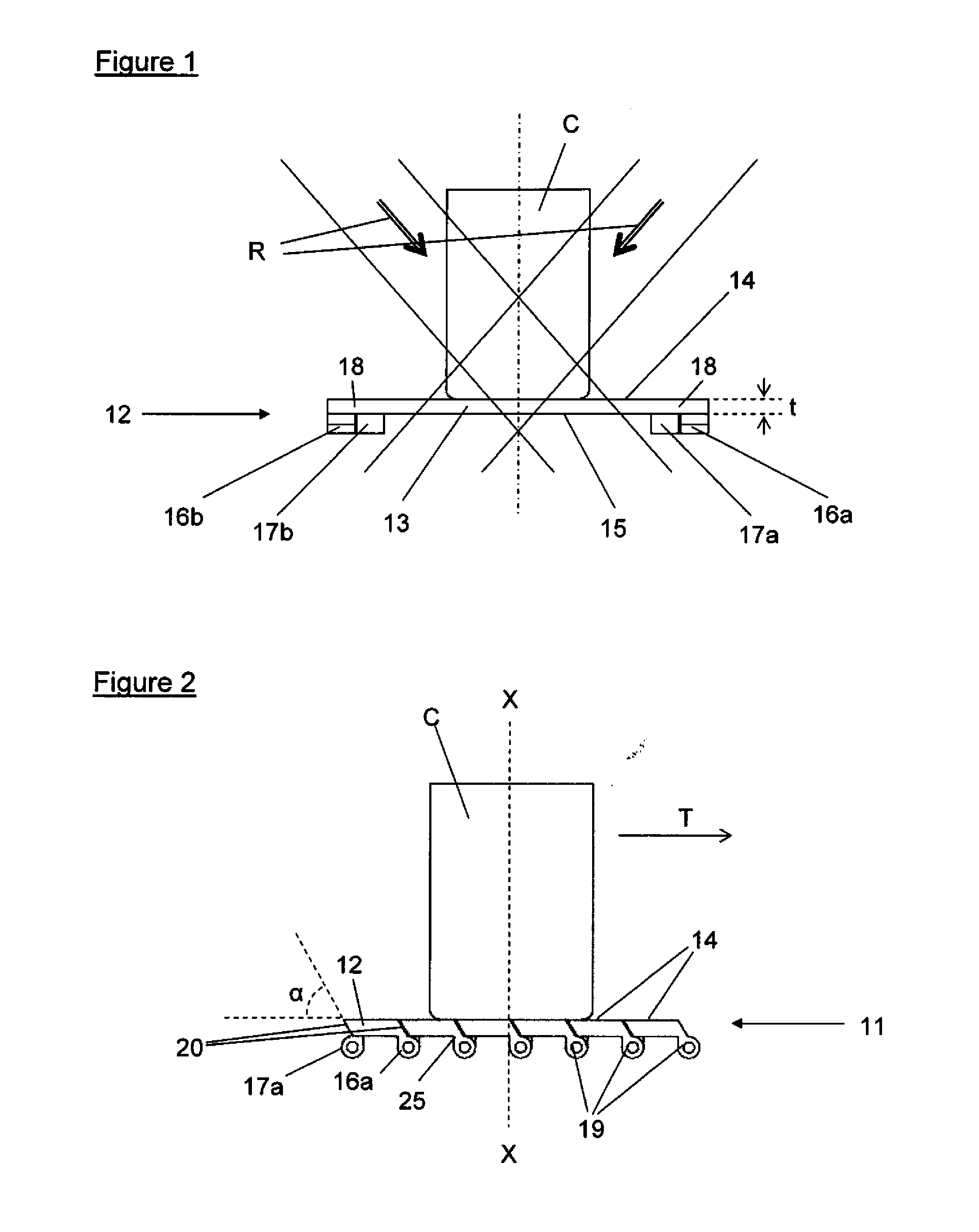
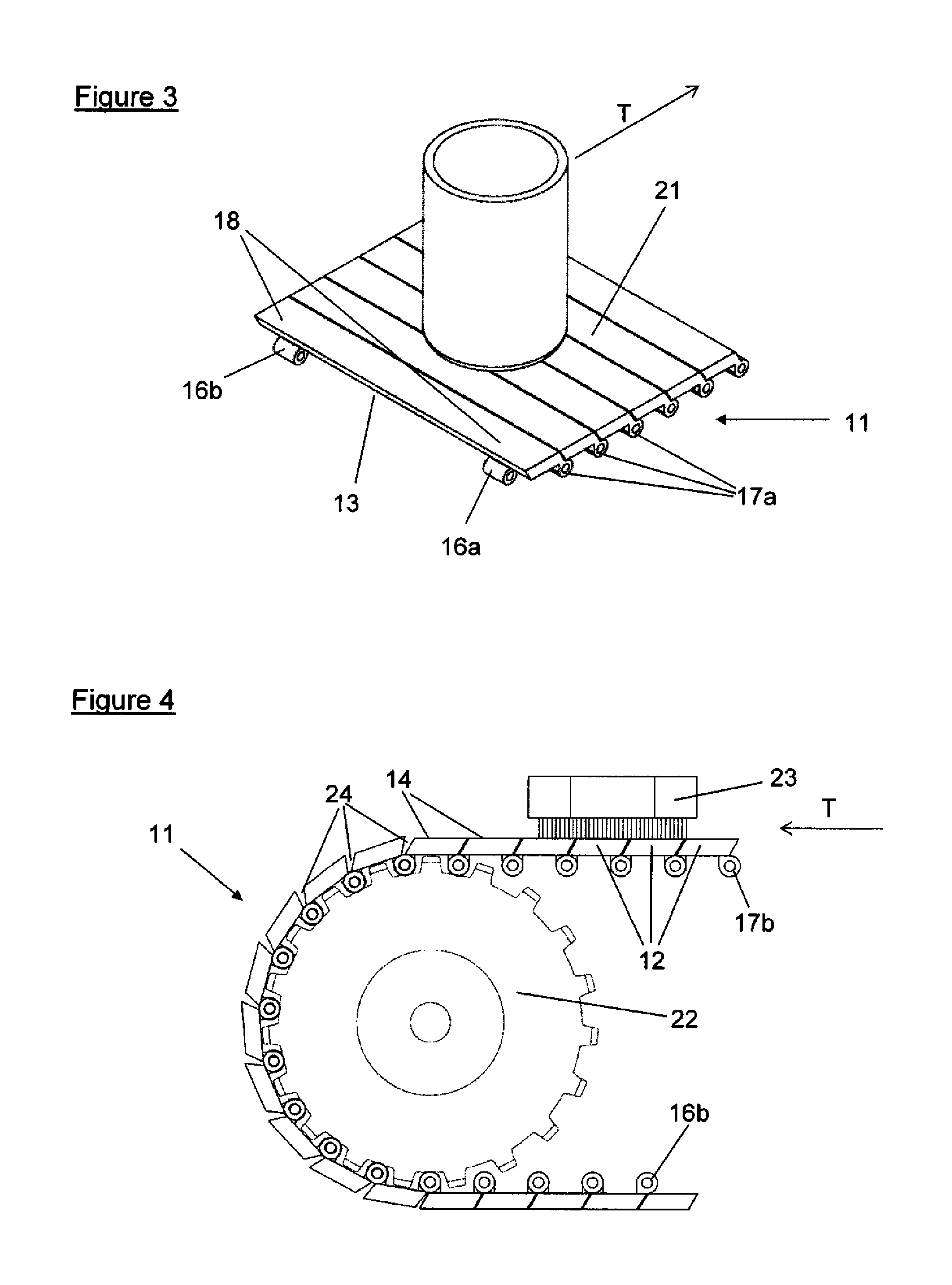
[0029]An exemplary embodiment of a conveyor chain 11 is shown in four different views in FIGS. 1 to 4. Viewed in the direction of movement of the conveyor chain, FIG. 1 schematically represents a conveyor chain segment 12 with a container C at the moment when the container C passes through the beams of a scanning radiation R of a radiographic inspection system (wherein the latter is not shown in the drawing). In this exemplary embodiment, the conveyor chain segment 12 has a flat topside 14 forming part of the transport surface 21 (see FIG. 3) of the conveyor chain 11. The mid-section 13 of the conveyor chain segment 12, which is traversed by the scanning radiation R, is of a substantially uniform thickness t. Hinge bearings are arranged on the underside 15 of the conveyor chain segment 12 in the outside border areas 18 that are not traversed by the scanning radiation R. In this embodiment, the part of the underside15 that covers the mid-section 13 is flat and parallel to the topsid...


PUM


Abstract

A conveyor chain comprising rigid segments which extend over a width of the chain and are configured at least in part as plates of a uniform thickness and density. The segments are connected together in a loop and have elements to couple each segment to a following segment and a preceding segment. Neighboring segments may flex against each other from a substantially straight line to a convex angle in relation to the loop, so that the chain is adapted to conform to rollers or sprockets, but is resistant to flexing in the opposite direction. The segments overlap each other to form a transport area of substantially uniform thickness and density to provide at least one substantially gapless band of substantially uniform transmissivity to radiation in the transport area, wherein the connector elements are located outside the transport area. A system comprising the chain is also provided.

Description

[0001]This application is a continuation of International Patent Application No. PCT / EP2010 / 057351, filed May 27, 2010, which claims priority to European Patent Application No. 09007252.1, filed May 29, 2009, each of which is hereby incorporated by reference in its entirety.BACKGROUND AND SUMMARY OF THE INVENTION[0002]Exemplary embodiments of the invention relate generally to a conveyor belt, more specifically a conveyor chain that is comprised of a multitude of rigid segments or links that are connected to each other in a closed loop, wherein each link is articulately hinged to a following link and a preceding link. Exemplary embodiments of the invention further relate to a radiographic inspection system that includes the conveyor chain as a component.[0003]One exemplary embodiment of an endless conveyor chain may be used in an inspection system in which the objects under inspection are transported by a conveyor belt or conveyor chain through an X-ray machine or other radiographic ...

Claims


Application Information

Patent Timeline
Patent Type & Authority Applications(United States)
IPC IPC(8): B65G17/40H05G1/00
CPCB65G17/08G01N23/083G01N2223/643
Inventor KING, NIGEL JOHN
Owner METTLER TOLEDO SAFELINE X RAY
Why Eureka
Try Eureka