Method and device for preventing slip of work piece

a work piece and workpiece technology, applied in the direction of grinding machine components, manufacturing tools, grinding machines, etc., can solve the problems of poor machining of work pieces, the pressing force of the center cannot be blindly increased, and the grinding accuracy of the work piece is reduced, so as to reliably prevent a slip and reduce the current value of the servo motor. , the effect of high accuracy

Inactive Publication Date: 2012-05-24
JTEKT CORP
View PDF11 Cites 10 Cited by
  • Summary
  • Abstract
  • Description
  • Claims
  • Application Information

AI Technical Summary

Benefits of technology

[0023]With the invention according to claim 1, before grinding, the step detection cycle that detects the limit current value for the servo motors, at which the work piece and the centers slip, is executed, and, during grinding, the grinding condition is changed to prevent a slip between the work piece and the centers in advance when any one of the current values of the servo motors has reached the slip threshold value set on the basis of the limit current value, so it is possible to implement safe grinding with no slip of the work piece. Moreover, not the non-slip condition is calculated through calculation but friction resistance at which a slip occurs is measured before grinding on the machine, so it is possible to carry out high accuracy measurement, and it is possible to reliably prevent a slip between the work piece and the centers.
[0024]With the invention according to claim 2, the slip detection cycle is configured to rotate at least one of the master main spindle and the slave main spindle by the servo motors to thereby detect the limit current value at which the work piece and the centers slip, so it is possible to measure friction resistance that causes a slip in a condition close to actual machining.
[0025]With the invention according to claim 3, the slip detection cycle is configured to rotate the master main spindle and the slave main spindle in opposite directions by the master servo motor and the slave servo motor to thereby detect the limit current value at which the work piece and the centers slip, so it is possible to set a smaller one of the current value of the master servo motor and the current value of the slave servo motor as an upper limit value.
[0026]With the invention according to claim 4, the grinding condition is changed by decreasing the infeed speed of the wheel head or controlling the pressing force of the centers, so, after any one of the current values of the servo motors has reached the slip threshold value set on the basis of the limit current value, the grinding condition is changed to make it possible to reduce the current values of the servo motors, and it is possible to reliably prevent a slip between the work piece and the centers.
[0027]With the invention according to claim 5, the center pressing device that automatically controls the center pressing force on the basis of grinding resistance that occurs during rough grinding, precise grinding and fine grinding is provided, so, during rough grinding having a large grinding resistance, the center pressing force is increased to prevent a slip of the work piece, while, during precise grinding and fine grinding, the center pressing force is reduced with a reduction in grinding resistance to minimize deformation of the work piece while preventing a slip of the work piece to thereby make it possible to implement highly accurate grinding.
[0028]With the invention according to claim 6, the center pressing device is configured to vary the center pressing force in a stepwise manner for each of rough grinding, precise grinding and fine grinding, so the center pressing force may be controlled on the basis of grinding resistance that occurs during rough grinding, precise grinding and fine grinding, and it is possible to minimize deformation of the work piece while preventing a slip of the work piece.

Problems solved by technology

On the other hand, as the pressing force of the centers is excessively increased, a work piece warps to lead to a decrease in grinding accuracy, so there are technical restrictions that the pressing force of the centers cannot be blindly increased.
Thus, depending on set center pressing force, the grinding resistance may be larger than the friction resistances of the centers and a slip may occur between the centers and a work piece to cause poor machining of the work piece.

Method used


Image

  • Method and device for preventing slip of work piece
  • Method and device for preventing slip of work piece
  • Method and device for preventing slip of work piece

Examples


Embodiment Construction

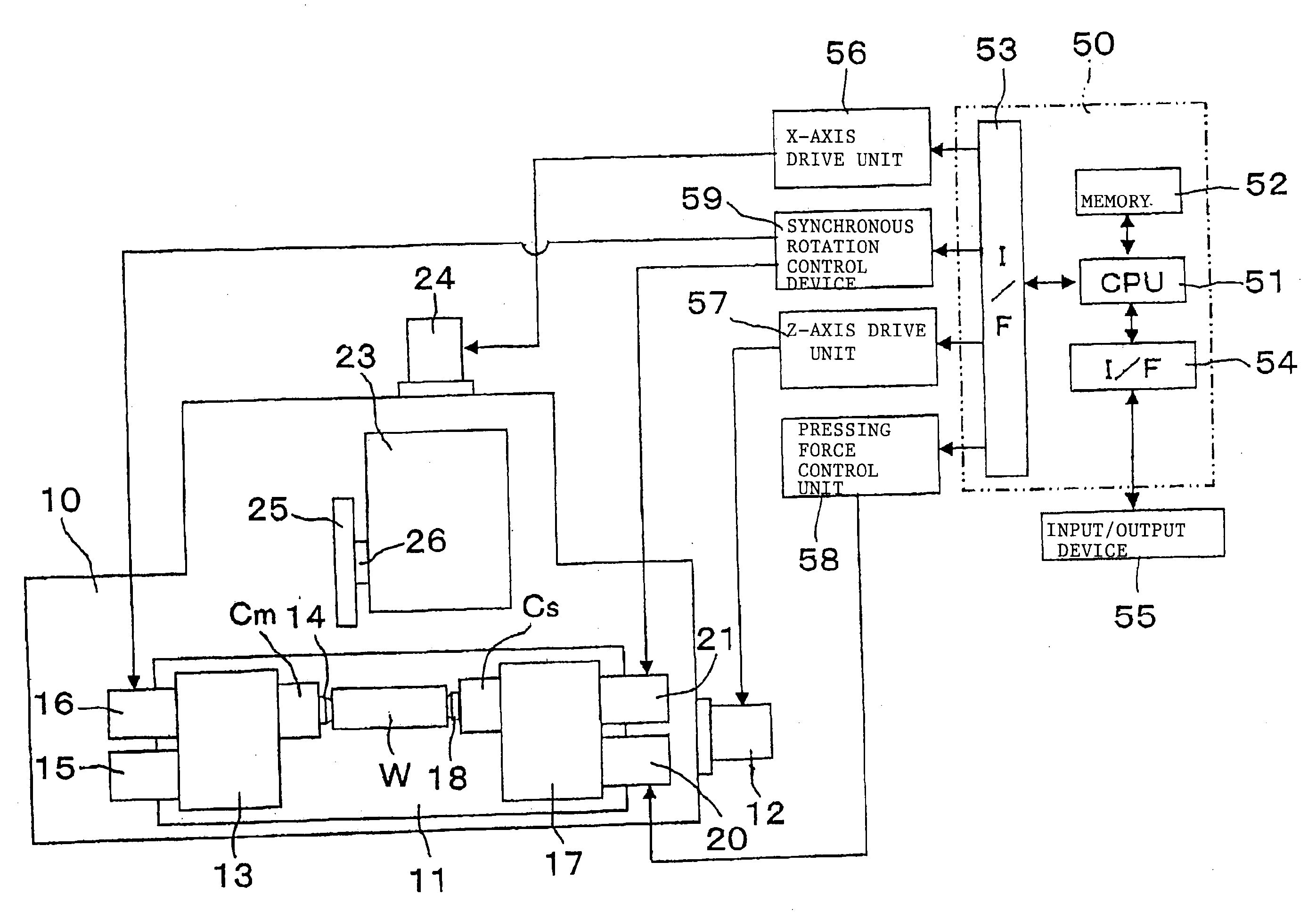
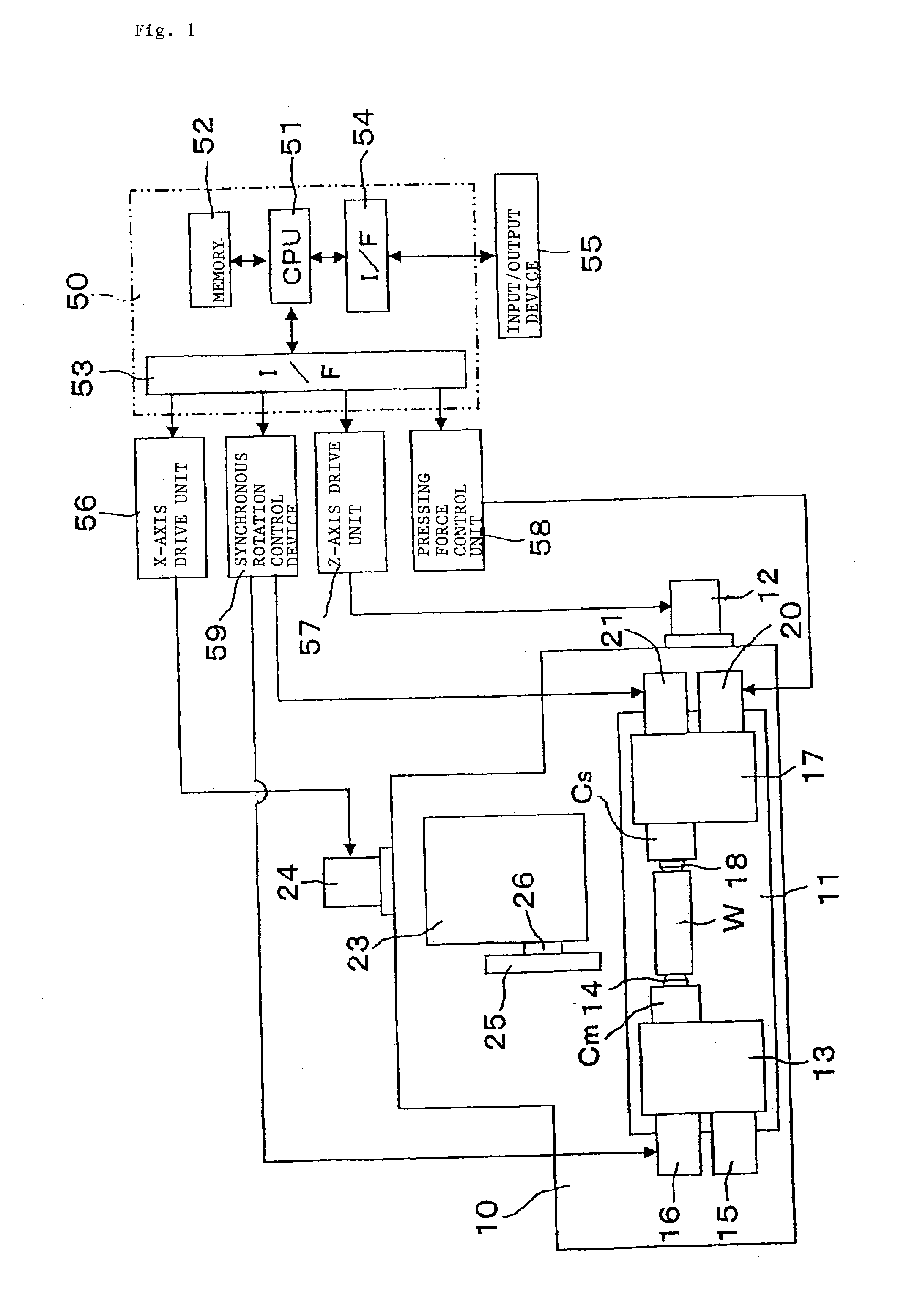
[0050]Hereinafter, an embodiment of the invention will be described with reference to the drawings. As shown in FIG. 1, a table 11 is guided and supported movably in a Z-axis direction (horizontal direction in FIG. 1) by a Z-axis servo motor 12 on a bed 10 of a grinding machine. A headstock 13 that rotatably supports a master main spindle Cm is installed on the table 11, and a center 14 that supports one end of a work piece W is mounted at the distal end of the master main spindle Cm. The master main spindle Cm is configured to move forward or backward by a predetermined amount in the axial direction by a forward / backward driving device 15, and is configured to be driven for rotation by a master servo motor 16.

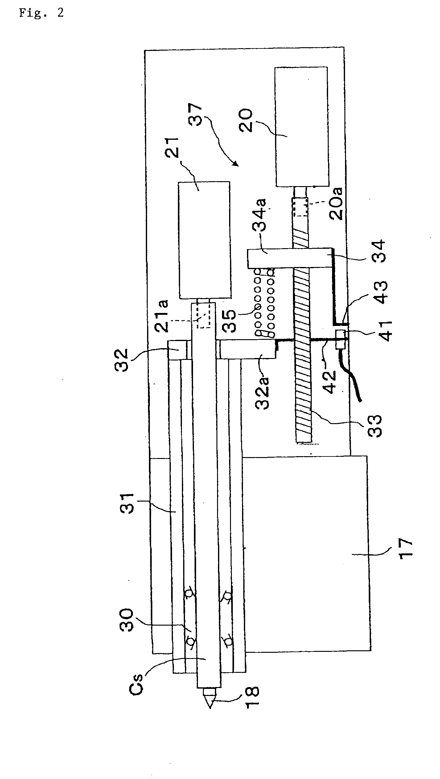
[0051]A tailstock 17 is installed at a position facing the headstock 13 on the table 11. A slave main spindle Cs is rotatably supported by the tailstock 17 coaxially with the master main spindle Cm, and a center 18 that supports the other end of the work piece W is mounted at ...


PUM

PropertyMeasurementUnit
friction forcesaaaaaaaaaa
pressing forceaaaaaaaaaa
forceaaaaaaaaaa

Abstract

A master servo motor and a slave servo motor that synchronously drive for rotation a master main spindle provided with a center that supports one end of a work piece and a slave main spindle provided with a center that supports the other end of the work piece are included. Before grinding, a slip detection cycle that detects a limit current value for the servo motors, at which the work piece and the centers slip, is executed and, during grinding, a grinding condition is changed to prevent a slip between the work piece and the centers in advance at the time when any one of current values of the servo motors has reached a slip threshold value set on the basis of the limit current value.

Description

TECHNICAL FIELD[0001]The invention relates to a method and device for preventing a slip of a work piece in a grinding machine that grinds the work piece in such a manner that both ends of the work piece are synchronously driven for rotation by the friction forces of centers.BACKGROUND ART[0002]There is known a grinding machine that increases the pressing force of centers to a work piece supported at both ends by the centers to synchronously drive both ends of the work piece for rotation with the friction forces of the centers to thereby grind the work piece as, for example, described in Patent Document 1. In the thus configured grinding machine, it is not necessary to chuck the end portions of a work piece or attach a drive fitting, so, for example, it is characterized in that the overall length of a cylindrical work piece may be ground without reclamping the cylindrical work piece, drive fittings, or the like, for various work pieces having different shapes may be not required, and...

Claims


Application Information

Patent Timeline
Patent Type & Authority Applications(United States)
IPC IPC(8): B24B51/00B24B41/06
CPCB24B5/045B24B49/16B24B49/10B24B41/062Y10T409/300896Y10T409/305656Y10T409/307336
Inventor MAKIUCHI, AKIRA
Owner JTEKT CORP
Why Eureka
Try Eureka