Computational load distribution in a climate control system having plural sensing microsystems

a climate control system and microsystem technology, applied in the field of system monitoring and control, can solve the problems of a relatively high computational load and a relative high computational complexity, and achieve the effects of increasing efficiency, reducing computational complexity, and reducing computational complexity

Active Publication Date: 2012-05-24
GOOGLE LLC
View PDF17 Cites 131 Cited by
  • Summary
  • Abstract
  • Description
  • Claims
  • Application Information

AI Technical Summary

Benefits of technology

[0003]Substantial effort and attention continues toward the development of newer and more sustainable energy supplies, the conservation of energy by increased energy efficiency remains crucial to the world's energy future. According to an October 2010 report from the U.S. Department of Energy, heating and cooling account for 56% of the energy use in a typical U.S. home, making it the largest energy expense for most homes. Along with improvements in the physical plant associated with home heating and cooling (e.g., improved insulation, higher efficiency furnaces), substantial increases in energy efficiency can be achieved by better control and regulation of home heating and cooling equipment. By activating heating, ventilation, and air conditioning (HVAC) equipment for judiciously selected time intervals and carefully chosen operating levels, substantial energy can be saved while at the same time keeping the living space suitably comfortable for its occupants.

Problems solved by technology

Such computational tasks, which are termed “characterization and / or optimization algorithms” hereinbelow for clarity of description and not by way of limitation, can be of relatively high computational complexity and therefore can represent a relatively high computational load.

Method used


Image

  • Computational load distribution in a climate control system having plural sensing microsystems
  • Computational load distribution in a climate control system having plural sensing microsystems
  • Computational load distribution in a climate control system having plural sensing microsystems

Examples


Embodiment Construction

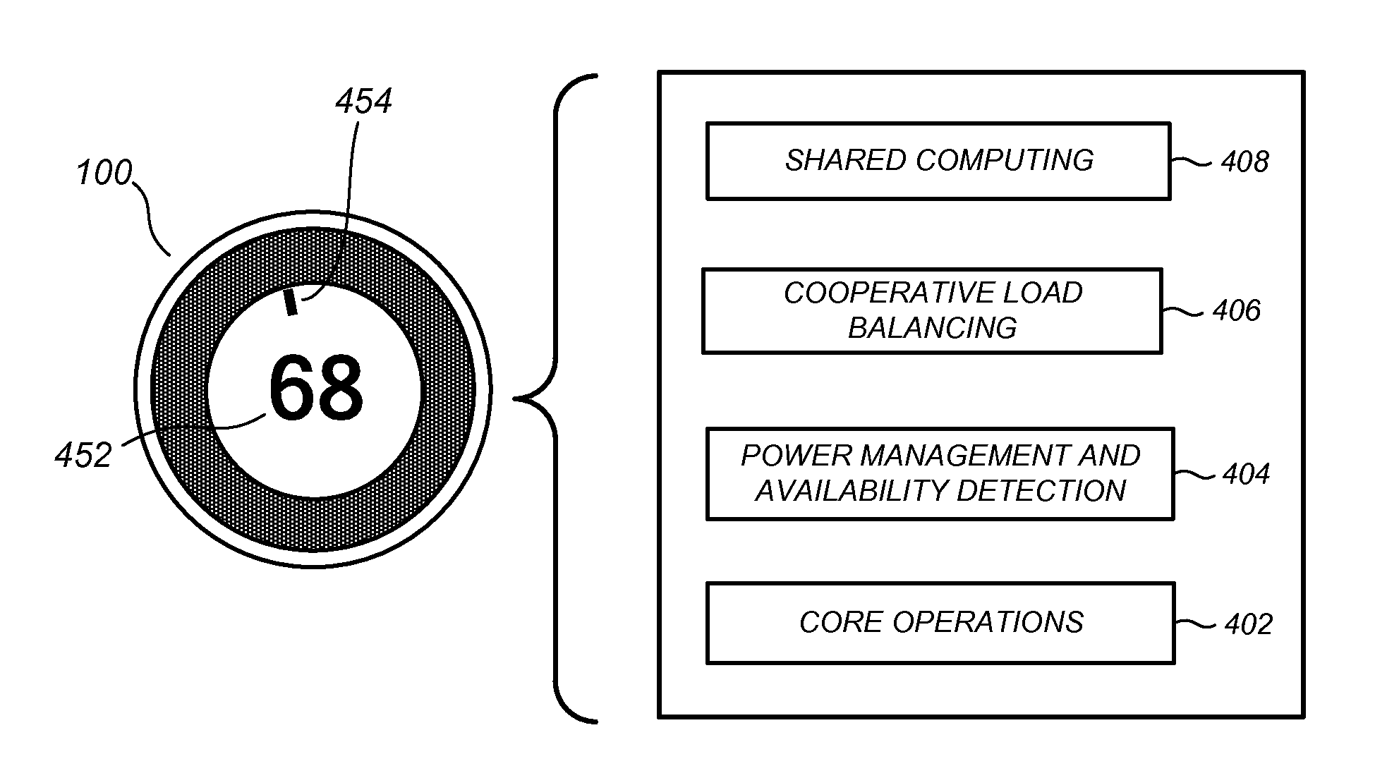
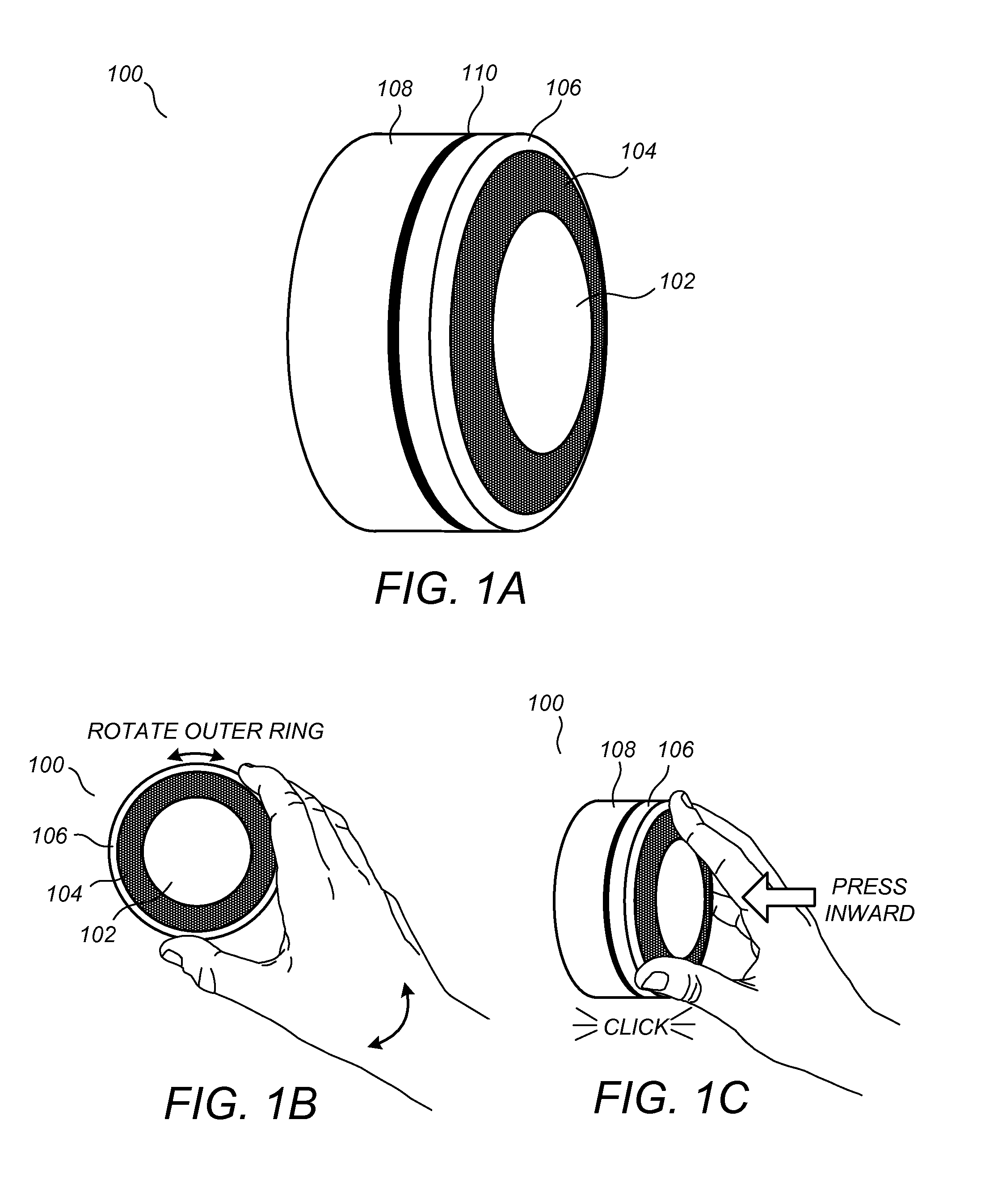
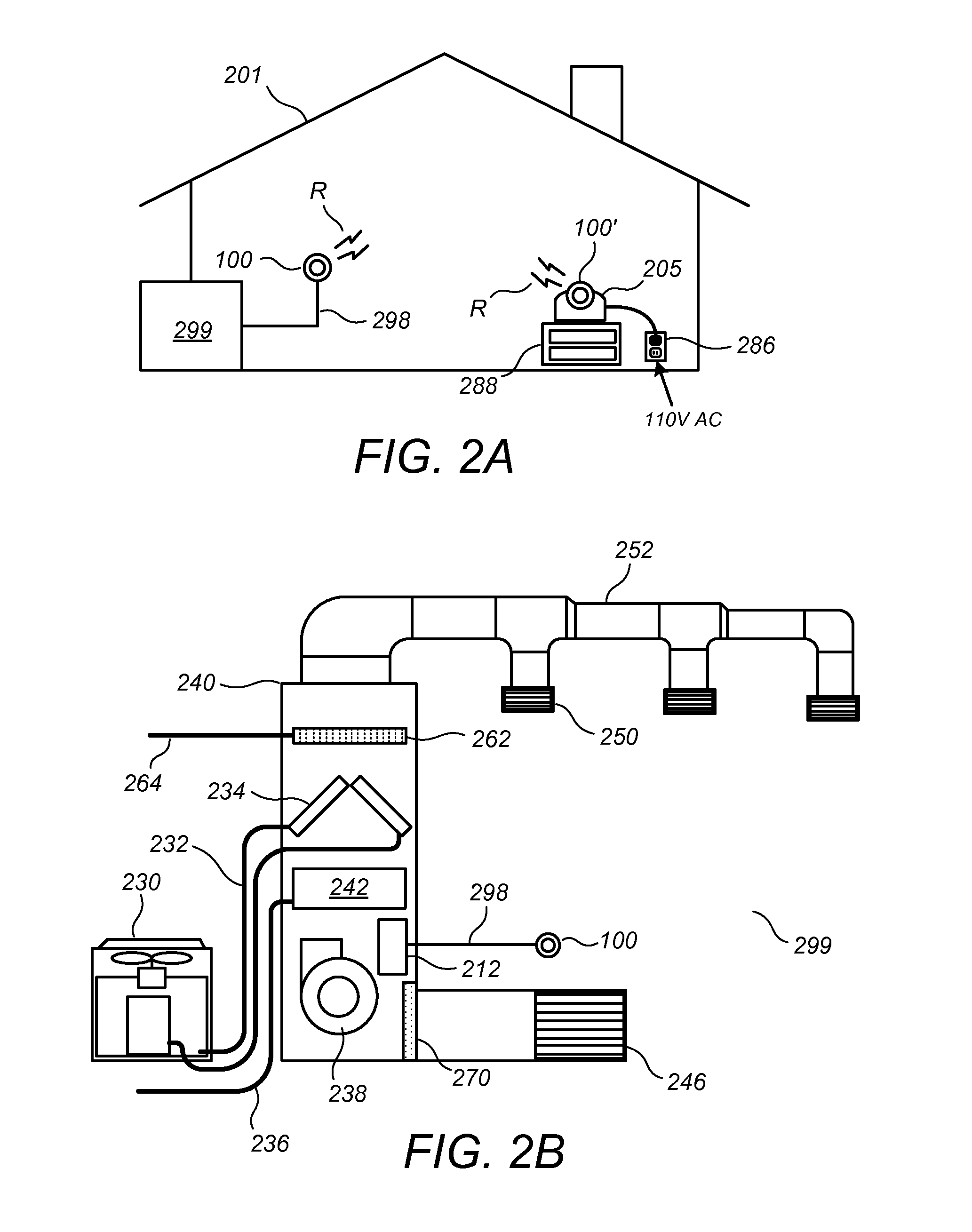
[0014]One or more of the embodiments described herein is particularly advantageous for use with climate control systems having plural wirelessly communicating sensing microsystems, such as those described in one or more of the commonly assigned incorporated applications, supra. More particularly, one or more of the embodiments described herein is particularly advantageous in the practical implementation of an easy-to-install, easy-to-administer, flexible, and scalable network of smart, visually appealing, “lightweight” sensing and control nodes, referenced herein as sensing microsystems, that cooperate to govern the operation of one or more HVAC systems in a manner that promotes an optimal balance of human comfort and energy efficiency for an enclosure, such as a residential or business building enclosure. By “lightweight,” it is meant that that the sensing microsystems are relatively compact and low-powered devices, comparable in size to handheld devices such as smartphones, and co...


PUM

PropertyMeasurementUnit
diameteraaaaaaaaaa
electrical poweraaaaaaaaaa
electrical energyaaaaaaaaaa

Abstract

Systems, methods, and related computer program products for controlling one or more HVAC systems using a distributed arrangement of wirelessly connected sensing microsystems are described. A plurality of wirelessly communicating sensing microsystems is provided, each sensing microsystem including a temperature sensor and a processor, at least one of the sensing microsystems being coupled to an HVAC unit for control thereof. The plurality of sensing microsystems is configured to jointly carry out at least one shared computational task associated with control of the HVAC unit. Each sensing microsystem includes a power management circuit configured to determine an amount of electrical power available for dedication to the at least one shared computational task. The at least one shared computational task is apportioned among respective ones of the plurality of sensing microsystems according to the amount of electrical power determined to be available for dedication thereto at each respective sensing microsystem.

Description

CROSS-REFERENCE TO RELATED APPLICATIONS[0001]This application claims the benefit of U.S. Prov. Ser. No. 61 / 429,093 filed Dec. 31, 2010 and U.S. Prov. Ser. No. 61 / 415,771 filed Nov. 19, 2010, each of which is incorporated by reference herein. The subject matter of this provisional patent specification relates to the subject matter of the following commonly assigned applications: U.S. Ser. No. 12 / 881,430 filed Sep. 14, 2010; U.S. Ser. No. 12 / 881,463 filed Sep. 14, 2010; U.S. Ser. No. 12 / 987,257 filed Jan. 10, 2011; U.S. Ser. No. 13 / 034,666 filed Feb. 24, 2011; U.S. Ser. No. 13 / 034,674 filed Feb. 24, 2011; and U.S. Ser. No. 13 / 034,678 filed Feb. 24, 2011. Each of the above-referenced patent applications is incorporated by reference herein. The above-referenced patent applications are collectively referenced hereinbelow as “the commonly assigned incorporated applications.”FIELD[0002]This patent specification relates to system monitoring and control, such as to the monitoring and control...

Claims


Application Information

Patent Timeline
Patent Type & Authority Applications(United States)
IPC IPC(8): G06F1/32G06F1/28G05D23/19F24F11/76H04W4/70
CPCF24F11/0012F24F2011/0068F24F2011/0073G05D23/1902G05D23/1917Y10T29/49826F24F11/0009H04W4/005F24D19/10F24D19/1084G05D23/19Y02B10/20Y02B10/70F24F2110/00F24F2110/10F24F2120/10F24F2140/60F24F11/32F24F2130/40F24F2120/20F24F11/62F24F11/63F24F11/64F24F11/56F24F11/61F24F11/46F24F11/52F24F11/39F24F11/47F24F11/89H04W4/70F24F11/30Y02D30/70F24F11/58F24F2140/00B01D46/0086G05B15/02H01R9/2416G05B13/0265
Inventor FADELL, ANTHONY MICHAELMATSUOKA, YOKYROGERS, MATTHEW LEESLOO, DAVID
Owner GOOGLE LLC
Why Eureka
Try Eureka