Light source device and projector

a light source device and projector technology, applied in lighting and heating apparatus, television systems, instruments, etc., can solve the problems of deteriorating the liquid crystal light valve, difficult quick lighting, and relatively short product life, and achieve high-quality image display and suppress brightness variations.

Active Publication Date: 2012-05-31
SEIKO EPSON CORP
View PDF15 Cites 74 Cited by
  • Summary
  • Abstract
  • Description
  • Claims
  • Application Information

AI Technical Summary

Benefits of technology

[0008]An advantage of some aspects of the invention is to provide a light source device capable of preventing the degradation of the luminance efficiency to thereby emit the intense (high-intensity) light. Another advantage of some aspects of the invention is to provide a projector having such a light source device, and capable of high-quality image display.

Problems solved by technology

However, the discharge lamp of this kind has a problem that the product life is relatively short, a problem that quick lighting is difficult, a problem that the ultraviolet light emitted from the lamp deteriorates the liquid crystal light valve, and so on.
Thus, it results in that the luminance efficiency (the proportion of the luminance amount of the fluorescent body with respect to the incident light intensity of the excitation light) is degraded.
Therefore, it is difficult to obtain a desired light intensity even in the case of using the light source disclosed in Document 1 and increasing the excitation light intensity attempting to obtain the intense light.
However, since the axes of the light beams emitted from the respective solid-state light sources are separate from each other in the solid-state light source array, if the solid-state light source array is used, there occurs the unevenness in the light intensity in the bundle of the light beams of the excitation light thus emitted in the solid-state light source array on the whole, such that the area in the vicinity of the light beam axis corresponding to each of the solid-state light source is bright while the area corresponding to the middle of the solid-state light sources is dark.
Therefore, it results in that the efficient luminance becomes difficult such that the fluorescence is emitted from the entire surface of the fluorescent body without causing the light saturation on the fluorescent body.
According to this configuration, it is difficult to generate the unevenness in the intensity distribution due to the transmission through the collimating lens in the excitation light entering the lens array, and it is easy to perform the averaging of the excitation light using the lens array and the light collection optical system.
Further, since the excitation light is not imaged at the focal position, the image of the excitation light blurs, and it is easy to average the light intensity.

Method used


Image

  • Light source device and projector
  • Light source device and projector
  • Light source device and projector

Examples


first embodiment

[0050]Hereinafter, a light source device and a projector according to a first embodiment of the invention will be explained with reference to FIGS. 1 through 13. It should be noted that in all of the drawings described below, the sizes and the ratios between the sizes of the constituents are arbitrarily made different from each other in order for making the drawings eye-friendly.

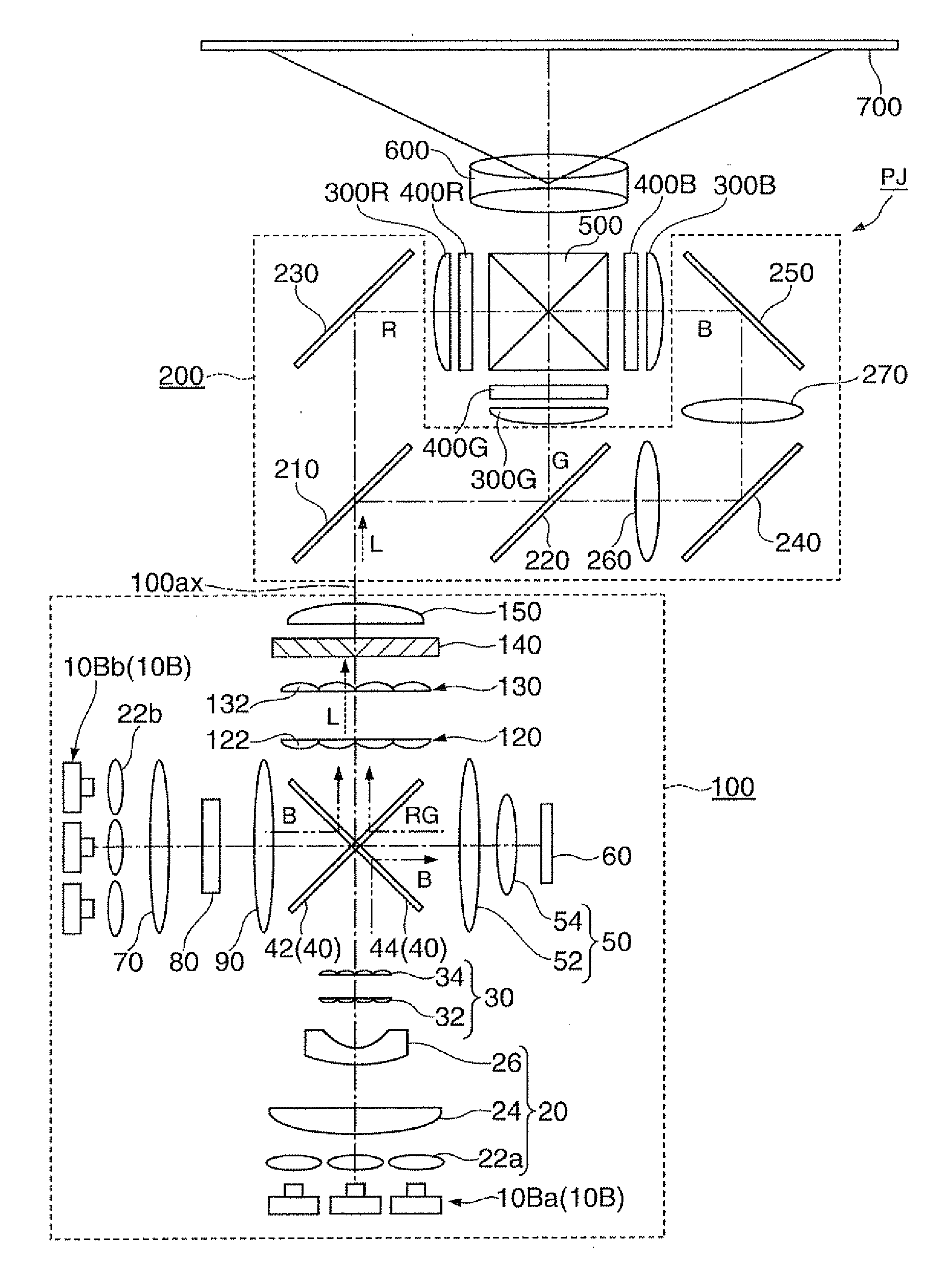
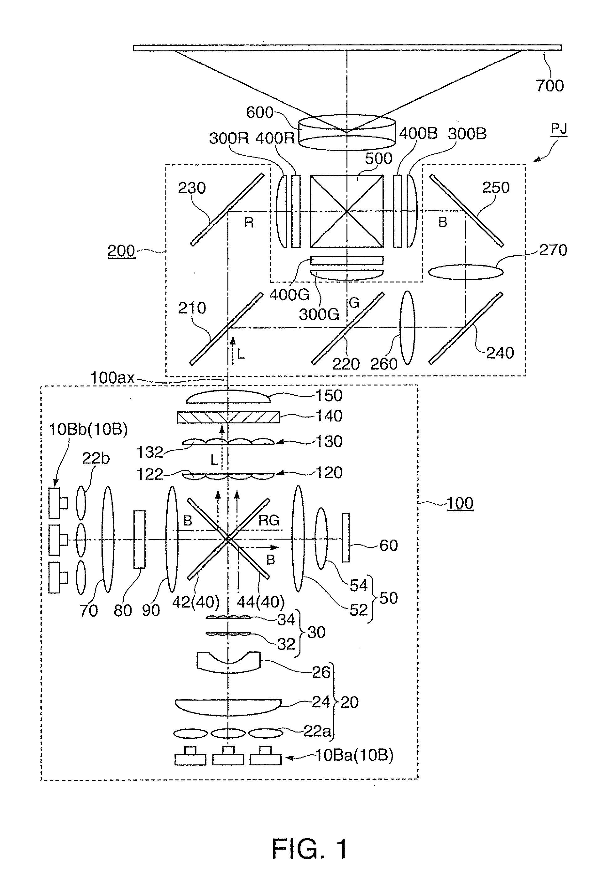
[0051]FIG. 1 is a schematic diagram showing the light source device 100 and the projector PJ according to the present embodiment. As shown in the drawing, the projector PJ includes the light source device 100, a color separation optical system 200, a liquid crystal light valve (light modulation element) 400R, a liquid crystal light valve 400G, a liquid crystal light valve 400B, a color combining element 500, and a projection optical system 600.

[0052]The projector PJ generally operates as follows. The light emitted from the light source device 100 is separated by the color separation optical system 200 into a...

second embodiment

[0138]FIG. 14 is an explanatory diagram of a light source device according to a second embodiment of the invention. In the following explanation, the constituents common to the present embodiment and the first embodiment are denoted by the same reference symbols, and the detailed explanation therefor will be omitted.

[0139]As shown in FIG. 14, a configuration of a light source device 104 is partially common to the light source device 100 according to the first embodiment. The difference is that the lens integrator does not form a pair, and the first lens array 32 is used alone. In the present embodiment, the overlapping optical system 50 functions as the light collection optical system of the embodiment of the invention.

[0140]FIGS. 15A and 15B are explanatory diagrams showing the function of the first lens array 32 and the overlapping optical system 50. In FIGS. 15A and 15B, the overlapping optical system 50 is schematically illustrated as a single convex lens for the sake of simplif...


PUM


Abstract

A light source device includes a light source section adapted to emit excitation light, a lens array adapted to divide the excitation light into a plurality of partial light beams, a light collection optical system adapted to collect the excitation light divided into the plurality of partial light beams, and a light emitting element adapted to emit fluorescence by being excited by the excitation light.

Description

BACKGROUND[0001]1. Technical Field[0002]The present invention relates to a light source device and a projector.[0003]2. Related Art[0004]In the past, in the projector field, it has been common that the discharge lamp such as a super-high pressure mercury lamp has been used as the light source. However, the discharge lamp of this kind has a problem that the product life is relatively short, a problem that quick lighting is difficult, a problem that the ultraviolet light emitted from the lamp deteriorates the liquid crystal light valve, and so on. Therefore, there is proposed a projector using a light source of a type used instead of the discharge lamp.[0005]For example, in the projector proposed in JP-A-2004-327361 (Document 1), there is used a light source which externally inputs excitation light to a fluorescent body, and then emits the luminescence (fluorescence) thus obtained. Specifically, in Document 1, the light source is proposed as a light source having the total area of the...

Claims


Application Information

Patent Timeline
Patent Type & Authority Applications(United States)
IPC IPC(8): G03B21/14F21V5/04
CPCG02B13/22G02B27/102G02B27/48G03B21/204H04N9/3164G03B21/208G03B33/06H04N9/3158H04N9/3161G03B21/2066G02F1/1335G03B21/14G03B21/20H04N5/74
Inventor AKIYAMA, KOICHI
Owner SEIKO EPSON CORP
Why Eureka
Try Eureka