Circuit switched millimeter wave communication network

a communication network and millimeter wave technology, applied in the field of communication networks, can solve the problems of not justifying the design and construction of fiber optic trunk lines can often take many months, and the cost of fiber optic trunk lines is high, and achieves high bandwidth, low latency middle-mile, and high-speed communication.

Inactive Publication Date: 2012-05-31
TREX ENTERPRISES CORP
View PDF2 Cites 77 Cited by
  • Summary
  • Abstract
  • Description
  • Claims
  • Application Information

AI Technical Summary

Benefits of technology

[0035]The present invention provides a high bandwidth, low latency middle-mile, last mile core communications network providing low-cost and high-speed communications among the users of the network. Embodiments of the invention include a number of network access points located at a number of spaced apart sites. At least some of these network access points in the network are in communication with each other via millimeter radio links. In preferred embodiments the millimeter radio links include two millimeter radios, one transmitting in the frequency range of 71-76 GHz and receiving in the frequency range if 81 to 86 GHz and the other radio transmitting in the frequency range of 81-86 GHz and receiving in the frequency range if 71 to 76 GHz. In these preferred embodiments each millimeter wave radio is equipped with an antenna designed to produce a millimeter wave beam with an angular spread of less than two degrees. A high-speed swit

Problems solved by technology

However, the construction of fiber optic trunk lines is expensive (sometimes very expensive) and the design and the construction of these lines can often take many months, especially if the route is over private property or produces environmental controversy.
Often the expected revenue from the potential users of a particular trunk line under consideration does not justify the cost of the fiber optic trunk line.
A typical cell can have hundreds of customers so the amount of information can be huge.
Telephone companies provide communications services to nearly all of the homes and offic

Method used


Image

  • Circuit switched millimeter wave communication network
  • Circuit switched millimeter wave communication network
  • Circuit switched millimeter wave communication network

Examples


Embodiment Construction

First Preferred Broad Band Network

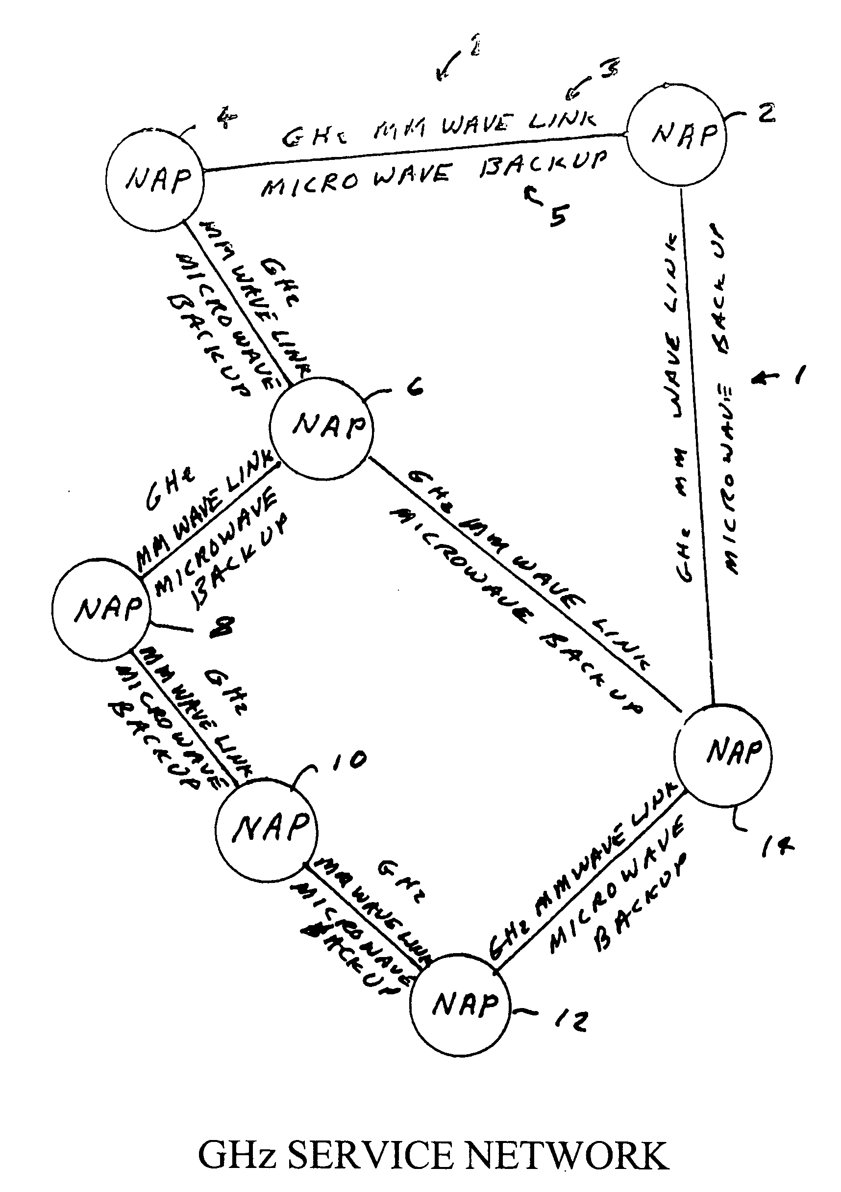
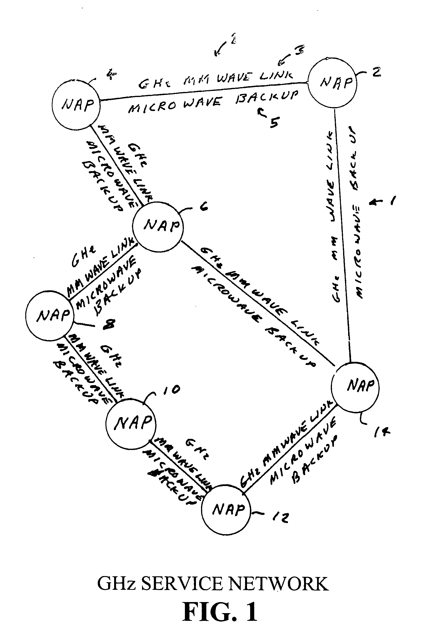
[0053]FIG. 1 is a sketch of a prototype broadband communication network substantially similar to a network developed and operated by Applicants covering a 50 square kilometer region on the Island of Oahu in Hawaii. This prototype network includes seven network access points 2, 4, 6, 8, 10, 12, and 14 referred to by Applicants as “NAPs”. These NAPs are in radio communication with through six radio channels 1 each channel including a two-radio millimeter wave radio link 3 operating at 71-76 GHz and 81-86 GHz. The radios are Models L2710 available from Loea Corporation with offices in Honolulu, Hi. These radios support data rates of 1 Gbps for the Gigabit Ethernet standard which was developed for fiber optic communication. Each of the millimeter wave links has a microwave backup radio link 5 operating at frequencies in the range of about 11 GHz which automatically continues the communication in case the millimeter wave link is broken due to heavy rain ...


PUM


Abstract

A high bandwidth, low latency middle-mile core communications network providing low-cost and high-speed communications among the users of the network. Embodiments of the invention include a number of network access points located at a number of spaced apart sites. At least some of these network access points in the network are in communication with each other via millimeter radio links with microwave backup links. In preferred embodiments the millimeter radio links include two millimeter radios, one transmitting in the frequency range of 71-76 GHz and receiving in the frequency range if 81 to 86 GHz and the other radio transmitting in the frequency range of 81-86 GHz and receiving in the frequency range if 71 to 76 GHz. In these preferred embodiments each millimeter wave radio is equipped with an antenna designed to produce a millimeter wave beam with an angular spread of less than two degrees. A high-speed switch is located at each network access point. The switches include a plurality of ports through which a plurality of network users transmits information through the network. Preferred embodiments utilize Ethernet switches programmed to encapsulate and tag incoming packets with a special set of tags which allow the tagging switch and other Ethernet switches in the network to direct the packets to one or more output ports of itself and/or one or more of the output ports of other Ethernet switches at one or more distant network access points, without a need for any of the network equipment to read any MAC or IP address information contained in the packets.

Description

CROSS REFERENCE TO RELATED APPLICATIONS[0001]This application is a continuation in part of U.S. patent application Ser. No. 12 / 228,114 formed Aug. 7, 2008 and Ser. No. 12 / 928,017 filed Nov. 30, 2010 which are incorporated herein by reference.FIELD OF THE INVENTION[0002]The present invention relates to communication networks and in particular to wireless communication networks.BACKGROUND OF THE INVENTIONTelecommunication Networks[0003]A telecommunications network is a collection of terminals, links and network access points which connect together to enable telecommunication between users of the terminals. Terminals refer to the end devices where information is originated or terminated. Devices such as phones, computers, printers, smart phones, personal digital assistants are all in the category of terminals. A network access point (sometimes called a “NAP” or a “node”) refers to the access point of a network where telecommunication information can pass through from its source termina...

Claims


Application Information

Patent Timeline
IPC IPC(8): H04W4/00
CPCH04W92/20
Inventor LEWIS, BRETTLOVBERG, JOHNHSIEH, TZU-CHIANGTANG, KENNETH Y.FEIN, ROBERT
Owner TREX ENTERPRISES CORP
Why Eureka
Try Eureka