
Structure of instrument panel parts

a technology of instrument panel parts and structure, which is applied in the direction of roofs, transportation and packaging, passenger space, etc., can solve the problems of large storage portion depth, difficult to ensure a storage portion with sufficient capacity, and difficult to make the bottom wall of the storage portion horizontal, so as to increase the support strength of the striker, narrow the distance between the tray and the glove box, and increase the rigidity of the lower edge portion

Inactive Publication Date: 2012-06-07
SUZUKI MOTOR CORP
View PDF2 Cites 18 Cited by
  • Summary
  • Abstract
  • Description
  • Claims
  • Application Information

AI Technical Summary

Benefits of technology

The present invention provides a structure for instrument panel parts with a storage portion above a glove box. The structure includes an opening portion, a separate tray, a striker engaging a lock of the glove box, and a reinforcement member supporting the striker. The lower side of the tray and the reinforcement member are fastened together to the instrument panel, which increases the support strength of the striker and the rigidity of the opening portion. The positioning precision is increased, and the number of man-hours is reduced. The tray is fixed to a member constituting a portion of the car frame, which improves the support rigidity of the tray and the striker. The structure achieves an enlarged storage volume within the limited volume of the instrument panel.

Problems solved by technology

If the instrument panel is provided with a shelve-shaped storage portion, which is inserted toward the inside of the instrument panel, then, when trying to mold it in one piece with the instrument panel, it is necessary to pull out the core (projecting portion) of the die, so that there are such problems as that it is hard to make the bottom wall of the storage portion horizontal with respect to the car body, or that a large depth of the storage portion cannot be attained, and thus it is difficult to ensure a storage portion with sufficient capacity.
Therefore, it does not contribute to increasing the rigidity of the edge of the opening portion of the glove box or the storage portion, and there is the risk of creaking noises, buckling and displacements.
In particular when a striker is attached, an impulsive load acts repeatedly when opening or closing the glove box, so that there was the risk that the attachment location of the fixing member is subject to deformations or breaking.
Therefore, it is necessary to supplement the strength of the rim of the opening portion separately with an additional reinforcing part or rib structure, so that there is no reduction of the number of parts after all or the mold shape becomes complicated.
Furthermore, since the fixing member is attached to the rear wall of the tray plate and the glove box is arranged below that, a portion corresponding to the vertical width of the fixing member will be wasted as dead space.

Method used


Image

  • Structure of instrument panel parts
  • Structure of instrument panel parts
  • Structure of instrument panel parts

Examples


Embodiment Construction

[0023]Referring to the accompanying drawings, the following is a detailed description of preferable embodiments of the present invention. All dimensions, materials and further specific numbers shown in the embodiments are given only by way of example, in order to aid the understanding of the invention, but are not meant to limit the present invention, unless this is explicitly stated so. It should be further noted throughout this specification and in the drawings, elements that have substantially the same functionality and / or structure are denoted by the same reference numerals, and their duplicate explanation has been omitted. Furthermore, elements that are not directly related to the present invention may not necessarily be shown in the figures.

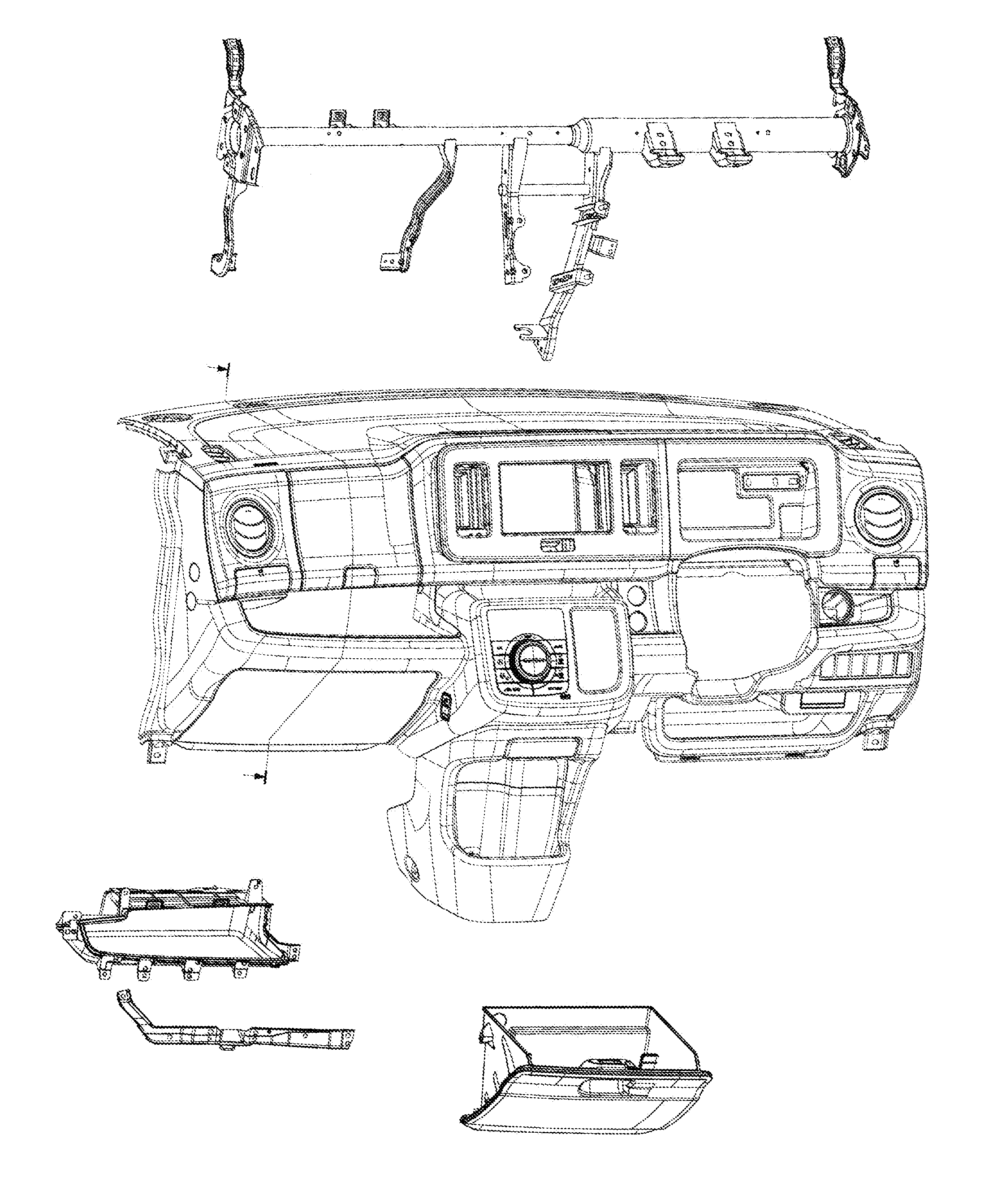
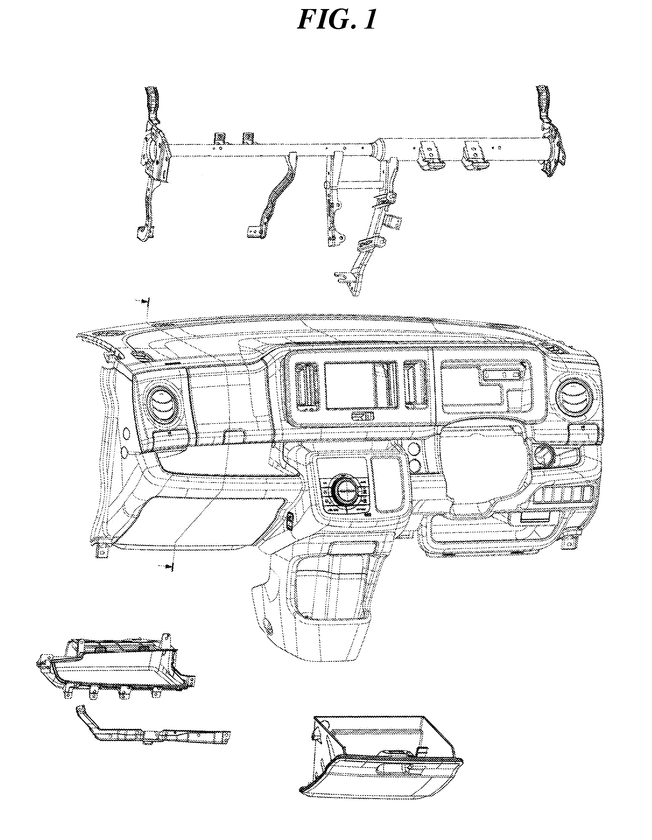
[0024]FIG. 1 is a diagram illustrating a structure of instrument panel parts according to an embodiment of the present invention. An instrument panel 100 as shown in FIG. 1 is an interior part that separates the engine room from the passeng...


PUM


Abstract

A structure of instrument panel parts is proposed that is capable of increasing the support strength of a striker and the rigidity of an opening portion, and with which an enlarged storage volume can be achieved. The structure of an instrument panel has a storage portion arranged above a glove box. The structure includes an opening portion for a tray provided above the glove box; a tray constituting the storage portion, the tray being provided as a separate member from the instrument panel and being attached to the opening portion for the tray; a striker engaging a lock of the glove box; and a substantially flat plate-shaped striker reinforcement member supporting the striker. The lower side of the tray and the striker reinforcement member are fastened together to the instrument panel.

Description

CROSS-REFERENCE TO RELATED APPLICATIONS[0001]This application is based upon and claims the benefit of priority from the prior Japanese Patent Application No. 2010-268736, filed on Dec. 1, 2010, the entire contents of which are incorporated herein by reference.BACKGROUND OF THE INVENTION[0002]1. Field of the Invention[0003]The present invention relates to a structure of instrument panel parts of an automobile, and more specifically to a structure for supporting a striker of a glove box.[0004]2. Background of the Invention[0005]Conventionally, a glove box is often provided in the instrument panel of an automobile. Furthermore, in recent years, in order to increase the on-board storage capabilities, a storage portion is sometimes provided above the glove box.[0006]If the instrument panel is provided with a shelve-shaped storage portion, which is inserted toward the inside of the instrument panel, then, when trying to mold it in one piece with the instrument panel, it is necessary to pu...

Claims


Application Information

Patent Timeline
Patent Type & Authority Applications(United States)
IPC IPC(8): B62D25/14
CPCB60K37/00B60R7/06B62D25/145
Inventor ONO, TOSHIYUKIATA, GOUKI
Owner SUZUKI MOTOR CORP
Learn More