Electrical impedance precision control of signal transmission line for circuit board

a technology of circuit board and impedance, applied in the direction of waveguide type devices, high-frequency circuit adaptations, non-metallic protective coating applications, etc., can solve the problems of signal reflection, loss or missing of signal in signal receiving, and poor impedance matching,

Active Publication Date: 2012-06-07
ADVANCED FLEXIBLE CIRCUITS
View PDF4 Cites 11 Cited by
  • Summary
  • Abstract
  • Description
  • Claims
  • Application Information

AI Technical Summary

Benefits of technology

[0010]Thus, an objective of the present invention is to provide a structure of flexible circuit board that allows for precision contro

Problems solved by technology

Due to such a structural arrangement, the electrical impedance of each signal transmission line of the circuit board may be varied, making it hard to control the precision of the electrical impedance.
In a practical application, such a circuit board may cause certain problems, including poor impedance matching, signal reflection, radiation of electromagnetic wave, loss or missing of signal in signal receiving, and deformation of signal waveform.
These problems cause sever influence on the circuit boards that are used in high precision electronic equipments.
This is especi

Method used


Image

  • Electrical impedance precision control of signal transmission line for circuit board
  • Electrical impedance precision control of signal transmission line for circuit board
  • Electrical impedance precision control of signal transmission line for circuit board

Examples


first embodiment

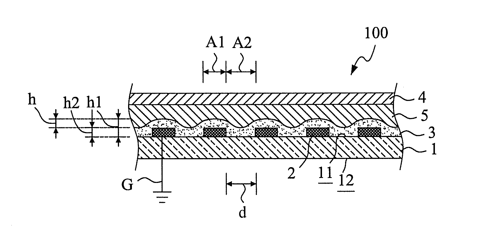
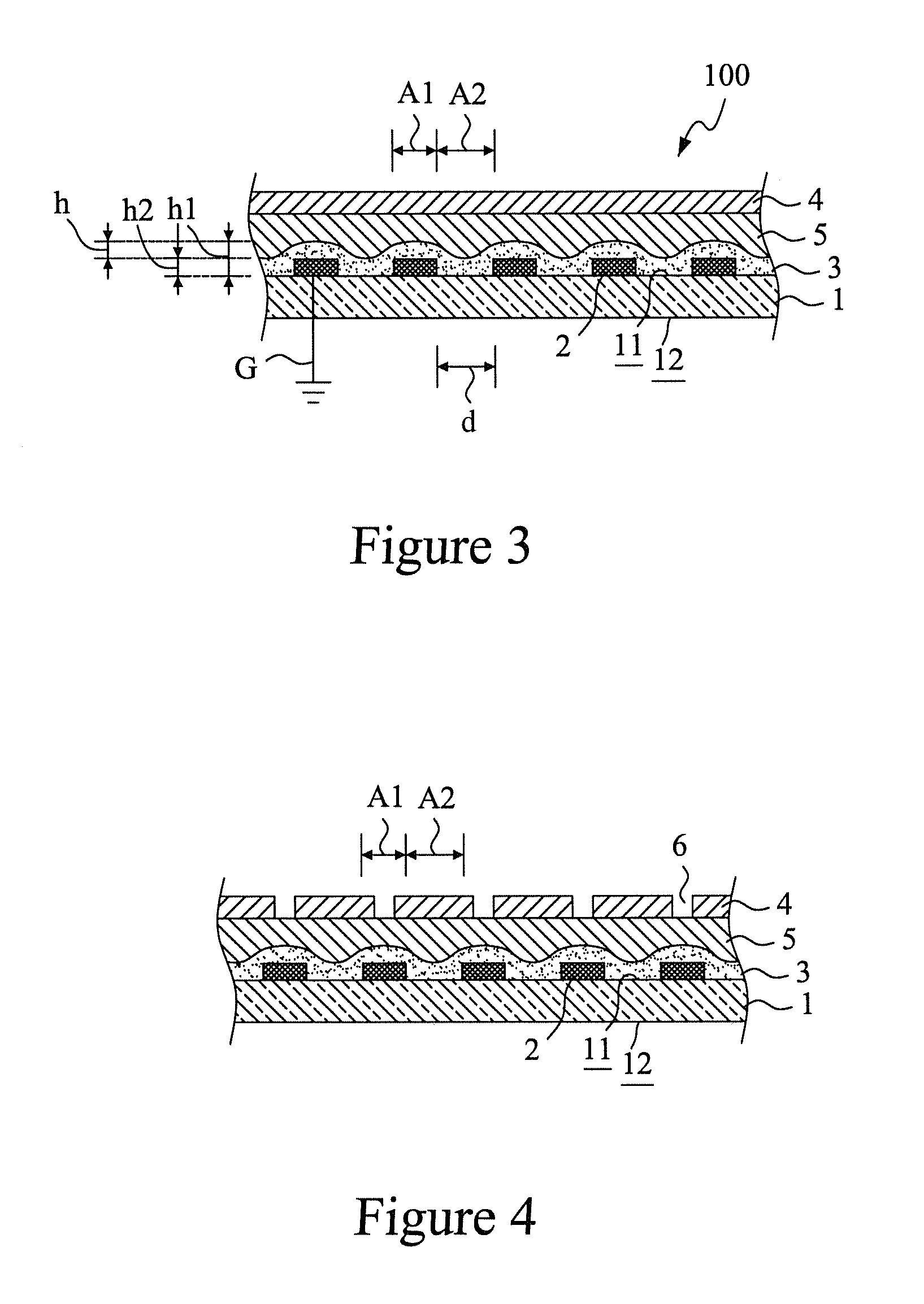
[0026]With reference to the drawings and in particular to FIG. 3, which is a cross-sectional view showing a first embodiment according to the present invention, as shown in the drawing, a substrate 1 has a first surface 11 and a second surface 12. The first surface 11 of the substrate 1 forms a plurality of parallel and spaced first signal transmission lines 2. The substrate 1 is preferably a flexible substrate, but can alternatively be a rigid substrate or other types of substrate (such as combined flexible and rigid board), and the substrate 1 can be a single-sided boards, double-sided board, or multiple-layered board.

[0027]The first signal transmission lines 2 are made of copper foil or a composite material and have a cross-sectional shape of rectangle, trapezoid, circle, ellipse, or other shapes. For the common practical etching process of circuit boards, the cross-sectional shape is generally rectangular or trapezoid, and for electronic flat cables, the cross-sectional shape ca...

sixth embodiment

[0041]FIG. 9 shows a cross-sectional view of a sixth embodiment according to the present invention. The instant embodiment provides a multiple-ply-stacked signal transmission circuit board based on the embodiment shown in FIG. 7. For example, a two-ply-stacked structure is shown, wherein a first signal transmission circuit board 100a comprises a substrate 1, first signal transmission lines 2, a first covering insulation layer 3, a first conductive shielding layer 4, a first flattening insulation layer 5, a second covering insulation layer 3a, a second conductive shielding layer 4a, and a second flattening insulation layer 5a. And similarly, a second signal transmission circuit board 100b comprises a substrate 1, first signal transmission lines 2, a first covering insulation layer 3, a first conductive shielding layer 4, a first flattening insulation layer 5, a second covering insulation layer 3a, a second conductive shielding layer 4a, and a second flattening insulation layer 5a. Th...


PUM


Abstract

Disclosed is a structure for precision control of electrical impedance of signal transmission circuit board. A substrate forms thereon a plurality of first signal transmission lines, and a first covering insulation layer is formed on a first surface of the substrate to cover a surface of each first signal transmission lines and each spacing section formed between adjacent first signal transmission lines. Each first signal transmission lines can transmit a differential mode signal or a common mode signal. At least one first flattening insulation layer is formed between a surface of the first covering insulation layer and a first conductive shielding layer so that the first flattening insulation layer fills up the height difference between the surface of each first signal transmission line and the spacing section associated with each first signal transmission line to thereby ensure a consistent distance between the signal transmission lines and the conductive shielding layer for realizing precision control of electrical impedance of the signal transmission circuit board.

Description

FIELD OF THE INVENTION[0001]The present invention relates to a structural design for electrical impedance of flexible circuit board, and in particular to a structural design of flexible circuit board for realizing precision control of electrical impedance of circuit boards or flexible flat cables.BACKGROUND OF THE INVENTION[0002]Various electronic devices use electrical circuit boards or flexible flat cables to arrange, position, and mount electrical parts and connectors, and to transmit electrical signals to desired destination functional elements. Manufacturing of circuit boards is often conducted by laying signal transmission traces, through wiring technology, on a surface of a substrate. The commonly known circuit boards are generally classified as rigid circuit boards and flexible circuit boards or flat cables.[0003]Taking a flexible flat cable that is commonly used in various electronic products, such as notebook computers, personal digital assistants, and mobile phones as an ...

Claims


Application Information

Patent Timeline
IPC IPC(8): H05K9/00
CPCH05K1/0218H05K1/0225H05K1/025H05K2201/0715H05K3/28H05K2201/0195H05K1/0253
Inventor LIN, GWUN-JINSU, KUO-FU
Owner ADVANCED FLEXIBLE CIRCUITS
Why Eureka
Try Eureka