Communication system, communication apparatus, communication method and computer program

Active Publication Date: 2012-06-07
PANTECH CORP
View PDF4 Cites 26 Cited by
  • Summary
  • Abstract
  • Description
  • Claims
  • Application Information

AI Technical Summary

Benefits of technology

[0062]According to the embodiments of present invention described above, it is possible to provide a communication system, a communication apparatus, a communication method, and a computer program which employ a superior relay mode capable of suitably performing intercell interference coordination.
[0063]Further, according to the embodiments of present invention described above, it is possible provide a communication system, a communication apparatus, a communication method and a computer program which are superior and capable of suitably solving issues of interference of adjacent cells involved in the introduction of relay technology while applying a fractional frequency repetition as intercell interference coordination.
[0064]Interference with the central frequency of an adjacent cell by a signal of the boundary frequency transmitted from a relay station can be adjusted so that improvement of the efficiency of frequency utilization can be realized, contributing to improvement of throughput for the user.
[0065]Interference with the central frequency of an adjacent cell by a signal of the boundary frequency transmitted from a relay station can be adjusted by restricting frequency bands

Problems solved by technology

Moreover, a higher operating frequency increases transmission losses and is sensitive to fading so that a coverage area of a base station deteriorates.
In the AF mode, it is difficult for the mobile station to improve the SNR and thus, it is necessary for the relay station to relay by using a region in which signal strength is sufficiently large.
Thus, when relay technology is introduced, an issue of delay caused by the mediation of a relay station needs to be sufficiently considered.
While the DF-type relay mode improves the SNR by a coding gain, a delay caused by decoding and recoding is significant.
ICIC is adopted, there is the possibility that a signal retransmitted from the relay station may interfere with adjacent cells.
The relay station is, when compared with th

Method used


Image

  • Communication system, communication apparatus, communication method and computer program
  • Communication system, communication apparatus, communication method and computer program
  • Communication system, communication apparatus, communication method and computer program

Examples


Embodiment Construction

[0099]An embodiment in which the present invention is applied to a mobile communication system such as LTE will be described in detail with reference to drawings.

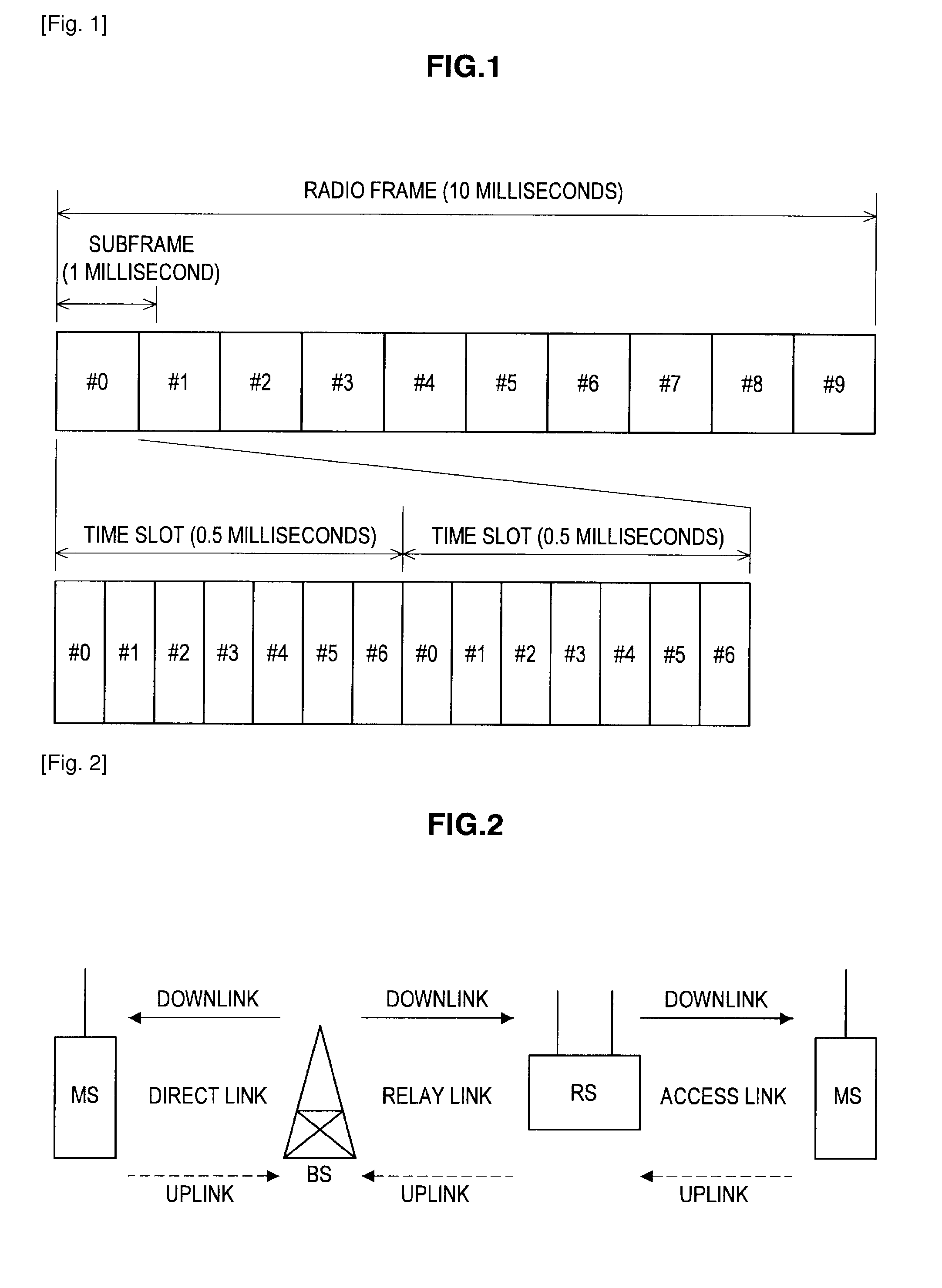
[0100]FIG. 1 shows a radio frame configuration of a downlink of LTE. As illustrated in FIG. 1, a radio frame is composed of three hierarchical layers of a time slot (Slot), a subframe (Subframe), and a radio frame (Radio Frame) in descending order of time unit.

[0101]A time slot of 0.5 millisecond is constituted by seven OFDM symbols (for normal unicast transmission) and becomes the unit of decode processing when received by a user (mobile station). A subframe of 1 millisecond is constituted by two consecutive time slots and becomes the unit of transmission time of a correction-coded data packet. A radio frame of 10 millisecond is constituted by 10 consecutive subframes (that is, 20 time slots) and becomes the basic unit for multiplexing of all physical channels.

[0102]Each user can perform communication without mutual interf...


PUM


Abstract

By deciding positions of frequencies used via a relay station by a system in advance for assignment of boundary frequencies, frequencies of a central frequency more likely to be affected by the relay station are also mapped by avoiding a signal thereof. Alternatively, an adjacent cell whose central frequency is affected changes depending on a position of the relay station and thus, locations set to be highly likely to interfere with the central frequency of the adjacent cell is reduced by setting a region of the boundary frequencies permitted to the relay station in accordance with the position of the relay station.

Description

TECHNICAL FIELD[0001]The present invention relates to a communication system, a communication apparatus, a communication method and a computer program in which a base station communications with a mobile station within a cell through the mediation of a relay station. In particular, the present invention relates to a communication system, a communication apparatus, a communication method and a computer program which employ a relay mode that applies intercell interference coordination.BACKGROUND ART[0002]Communication services become increasingly diverse with widespread use of information processing and information communication technology and in particular, development of mobile communication such as mobile phone is remarkable. Currently, 3GPP (Third Generation Partnership Project) is working on standardization of the world standard “IMT (International Mobile Telecommunications)-2000” of a third-generation (3G) mobile communication system drafted by ITU (International Telecommunicati...

Claims


Application Information

Patent Timeline
IPC IPC(8): H04W72/04H04W88/04
CPCH04L5/0073H04W72/08H04W72/10H04B7/2606H04W84/047H04L5/0062H04L5/0007H04L5/0094H04J11/005H04W72/54H04W72/56H04L5/0037H04B7/15542H04W72/04
Inventor TAKANO, HIROAKI
Owner PANTECH CORP
Why Eureka
Try Eureka