Low mass solid oxide fuel device array monolith

a fuel cell and monolithic technology, applied in the field of solid oxide fuel cell array monoliths, can solve the problems of limited thermal cycling rate and start-up time performance of the conventional sofc device assembly, relative poor gravimetric power density compared to conventional power generation devices, and low gravimetric power density, so as to reduce the mass, minimize the start-up fuel penalty, and high gravimetric power density

Inactive Publication Date: 2012-06-07
CORNING INC
View PDF1 Cites 16 Cited by
  • Summary
  • Abstract
  • Description
  • Claims
  • Application Information

AI Technical Summary

Benefits of technology

[0012]Some of the advantages of the exemplary embodiments of the SOFC device array monoliths is that they are especially suitable for mobile and portable applications because they are: (i) scalable (the size of fuel cell devices can be scaled up or down), and the number of the devices in device array monoliths can be increased or decreased, based on the application, and (ii) have a substantially reduced mass needed to ...

Problems solved by technology

Typical SOFC stacks target stationary applications, are large and heavy, and have relatively poor gravimetric power density compared to conventional power gene...

Method used


Image

  • Low mass solid oxide fuel device array monolith
  • Low mass solid oxide fuel device array monolith
  • Low mass solid oxide fuel device array monolith

Examples


example 1

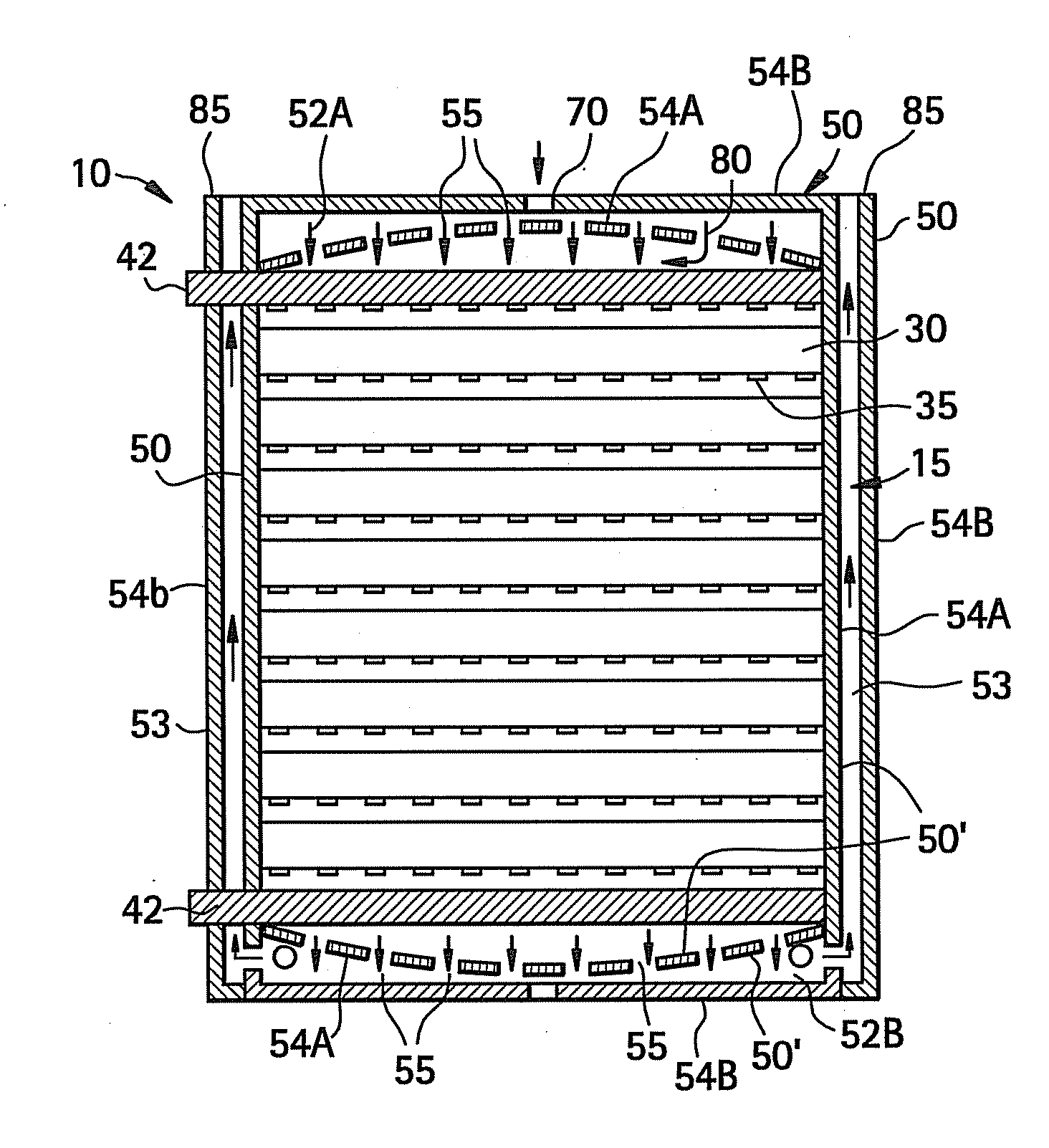
[0063]This example illustrates an ultra-low thermal mass fuel cell device array monolith 10 utilizing a plurality of frit bonded fuel cell devices.

SOFC 4-Port Monolith.

[0064]The following is a description of the process for fabrication of one embodiment of the SOFC device array monolith 10. The SOFC device array monolith 10 of this embodiment is an internally-manifolded monolith comprising of two fuel cell devices sandwiched between blank electrolyte sheets.

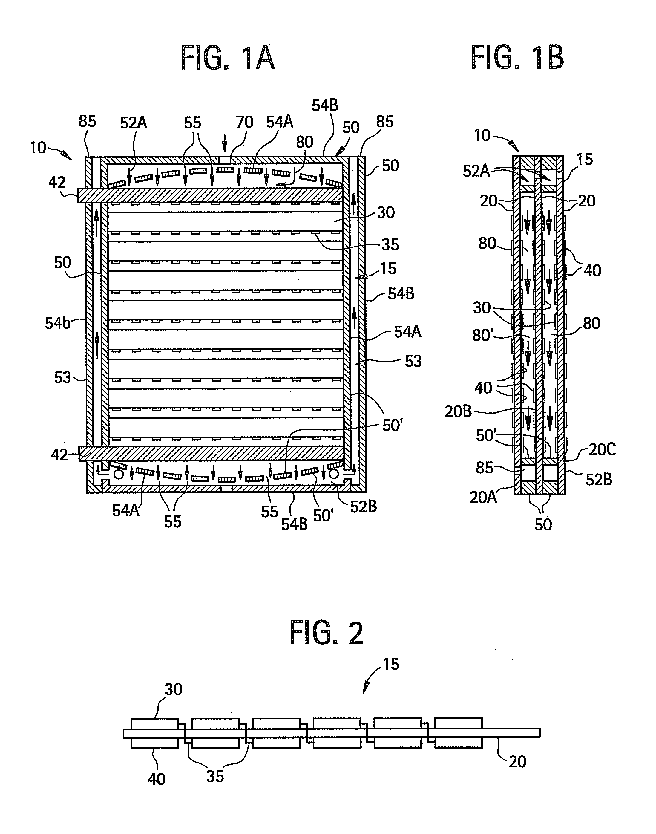
[0065]First, we fabricated two planar, mechanically flexible, multi-cell fuel cell devices 15 similar to that shown in FIG. 2. In this exemplary embodiment, the dimensions of the fuel cell devices 15 are 12 cm×15 cm. The fuel cell devices 15 have an unprinted border (i.e., at least a portion of the border boarder has no electrodes, or bus bars) available for deposition of patterned frit (material 50), so that material 50 does not contact the active electrode regions. Steps to fabricate the monolith (fuel cell device array monolit...

example 2

[0088]The internally manifolded device array monolith 10 of this and other embodiments of the design offers outstanding gravimetric and volumetric power density potential. The power output of the device array monolith 10 is a function of a number of parameters including cell power density, active cell area per device, and the number of devices in the device array monolith 10. Gravimetric power density is the power output divided by the device array monolith 10 mass, and is principally a function of the frit bead weight used in construction of the device array monolith 10. Volumetric power density is power output divided by device array monolith 10 volume, and is principally a function of the device to device spacing.

[0089]The device array monolith 10 shown schematically in FIG. 9 includes eight 12 cm×15 cm fuel cell devices 15 sandwiched between two 12 cm×15 cm electrolyte sheets 20. The fuel cell devices 15 and the electrolyte sheets 20 are joined by sintered frit. The contribution...

example 3

[0092]The lightweight design of device array monolith 10 is well suited for use in portable applications including mobile vehicles. For vehicle application, some of the important parameters are start-up time and fuel penalty. As noted previously, in the embodiments descried herein the start-up time is improved, due to improved thermal shock tolerance inherent with a low thermal mass mismatch between the frame and devices in the device array monoliths. Fuel penalty is largely determined by the stack heat device array monoliths 10. In a simple model which neglects heat loss from the stack as a first approximation, the following relation holds for mass of fuel required to heat the stack to operating temperature:

mf=nDAM(mCp)DAMLHVfT-T∞-(1+AFR)Cp,air

where: mf is the mass of fuel / gasoline (grams); nDAM is the number of device array monoliths in stack; (mCp)DAM is the heat capacity of device array monolith (J / K); LHVf is Lower Heating Value of the Fuel (Gasoline@ 42 MJ / kg); T is the target...


PUM

PropertyMeasurementUnit
Power densityaaaaaaaaaa
Timeaaaaaaaaaa
Flow rateaaaaaaaaaa

Abstract

According to one embodiment of the invention a fuel cell device array monolith comprises at least three planar electrolyte sheets having two sides. The electrolyte sheets are situated adjacent to one another. At least one of the electrolyte sheets is supporting a plurality of anodes situated on one side of the electrolyte sheet; and plurality of cathodes situated on the other side of the electrolyte sheet. The electrolyte sheets are arranged such that the electrolyte sheets with a plurality of cathodes and anodes is situated between the other electrolyte sheets. The at least three electrolyte sheets are joined together by sintered fit, with no metal frames or bipolar plates situated therebetween.

Description

[0001]This application claims the benefit of priority under 35 USC 119(e) of U.S. Provisional Application Ser. No. 61 / 220,783 filed on Jun. 26, 2009.BACKGROUND[0002]1. Field[0003]The present invention relates generally to fuel cell array assemblies, and more particularly to the Solid Oxide Fuel Cell device array monoliths.[0004]2. Technical Background[0005]Solid Oxide Fuel Cell (SOFC) systems show promise for highly efficient conversion of hydrocarbon fuels to electricity. Typical SOFC stacks target stationary applications, are large and heavy, and have relatively poor gravimetric power density compared to conventional power generation devices. Conventional SOFC fuel cell device assemblies include large and heavy components such as thick ceramic plates or tubes, metal supports, metal frames, and bipolar plates. Often these components are chosen in order survive thermal strains associated with high temperature operation. As a consequence, gravimetric power density, thermal cycling ra...

Claims


Application Information

Patent Timeline
IPC IPC(8): H01M8/24C03B29/00H01M8/10
CPCH01M8/124H01M8/2435Y02E60/525H01M2008/1293Y02E60/521H01M8/2465Y02P70/50Y02E60/50H01M8/2483H01M8/2404H01M8/12H01M8/24H01M8/02
Inventor BADDING, MICHAEL E.BOUTON, WILLIAM JOSEPHBROWN, JACQUELINE LESLIEKESTER, LANRIKPOLLARD, SCOTT CHRISTOPHERTEPESCH, PATRICK DAVID
Owner CORNING INC
Why Eureka
Try Eureka