
Photocatalytic coating, photocatalytic coating film and laminated coating film structure

a photocatalytic coating and coating film technology, applied in the direction of organic compound/hydride/coordination complex catalyst, physical/chemical process catalyst, metal/metal-oxide/metal-hydroxide catalyst, etc., can solve the problem of eroded coating per se, etc., and achieve strong hydrophobic tendency and promote bacteria or mold growth

Inactive Publication Date: 2012-06-07
METAL TECH CO LTD +2
View PDF4 Cites 13 Cited by
  • Summary
  • Abstract
  • Description
  • Claims
  • Application Information

AI Technical Summary

Benefits of technology

The present invention provides a photocatalytic coating that can resist erosion and has strong hydrophobic properties. The coating is made by dispersing or dissolving a photocatalyst, a tetrafluoro-ethylene-based resin, a compound containing metal ion, and an electrically neutral surfactant in a solvent. The coating can be applied to various industrial products, such as textiles, building materials, and in-mold injection molded products. The addition of an adsorbent with porosity and the use of a hydroxide containing metal ion further enhance the properties of the coating.

Problems solved by technology

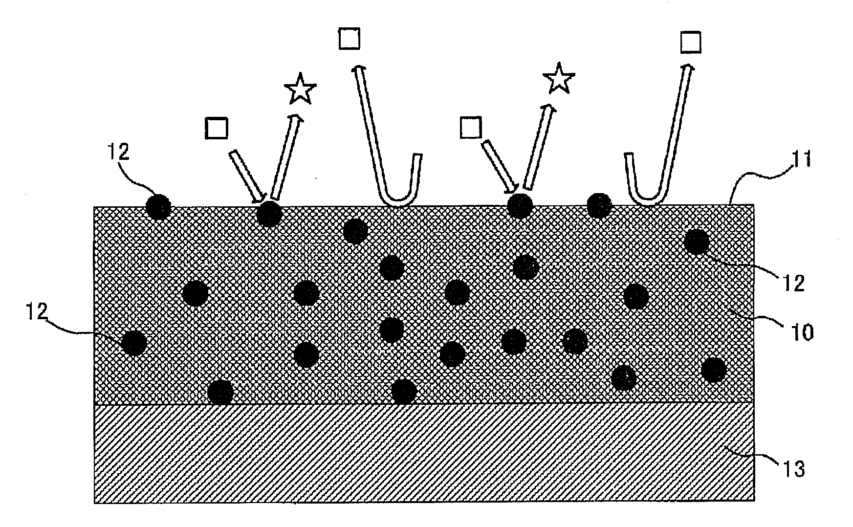
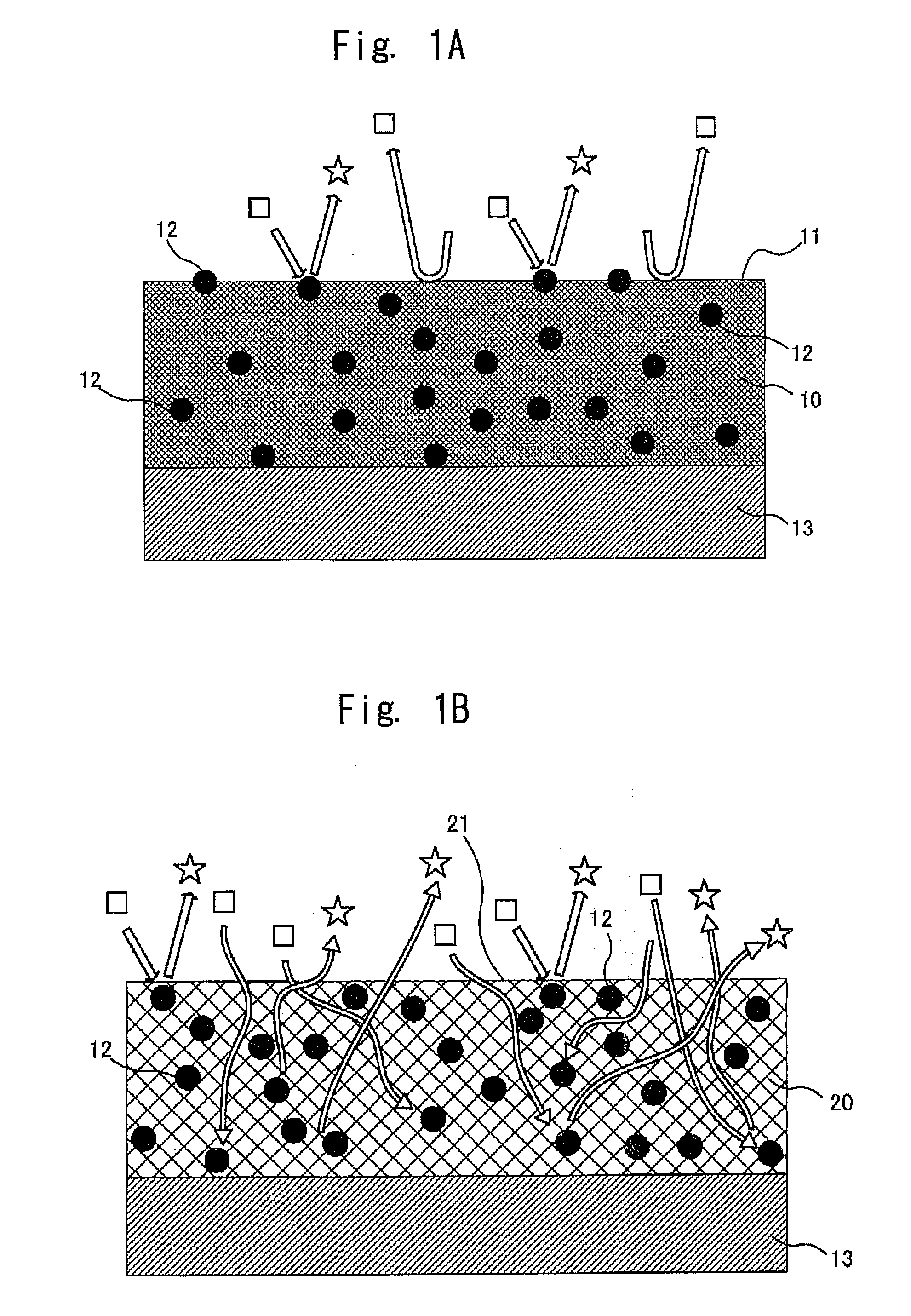
However, the above-mentioned photocatalytic coating has a drawback that the coating per se is eroded when the photocatalyst is excited.
Further, when the photocatalytic coating is applied to the wall surfaces or tiles expecting an antibacterial effect and an antifungal effect (hereinafter simply also referred to as “antibacterial effect”), moisture is adsorbed in a coating surface due to a super hydrophilicity effect of the photocatalyst thus giving rise to a drawback that the growth of bacteria or mold is promoted.

Method used


Image

  • Photocatalytic coating, photocatalytic coating film and laminated coating film structure
  • Photocatalytic coating, photocatalytic coating film and laminated coating film structure
  • Photocatalytic coating, photocatalytic coating film and laminated coating film structure

Examples


Embodiment Construction

[0062]Reference will now be made in detail to several embodiments of the invention that are illustrated in the accompanying drawings. Wherever possible, same or similar reference numerals are used in the drawings and the description to refer to the same or like parts or steps. The drawings are in simplified form and are not to precise scale. For purposes of convenience and clarity only, directional terms, such as top, bottom, up, down, over, above, and below may be used with respect to the drawings. These and similar directional terms should not be construed to limit the scope of the invention in any manner. The words “connect,”“couple,” and similar terms with their inflectional morphemes do not necessarily denote direct and immediate connections, but also include connections through mediate elements or devices.

The present invention provides a photocatalytic coating prepared by dispersing or dissolving a photocatalyst, a tetrafluoro-ethylene-based resin obtained by graft polymerizat...


PUM

PropertyMeasurementUnit
temperatureaaaaaaaaaa
thicknessaaaaaaaaaa
dynamic contact angleaaaaaaaaaa

Abstract

Provided is a photocatalytic coating in which the coating per se is hardly eroded even when a photocatalyst is excited and a coating surface having strong hydrophobic tendency can be formed. The photocatalytic coating is prepared by dispersing or dissolving at least a photocatalyst, a tetrafluoro-ethylene-based resin obtained by graft polymerization of a sulfonic acid, a compound containing metal ion having an ionic radius not less than an ionic radius of calcium and / or complex ion having an ionic radius not less than the ionic radius of calcium into a solvent. Further, hydroxide is used as the compound containing the metal ion or an electrically neutral surfactant is added to the photocatalytic coating.

Description

CROSS REFERENCE TO RELATED APPLICATIONS[0001]This application claims priority from International Patent Application (PCT) Serial No. PCT / JP2010 / 056547, filed Apr. 12, 2010, and International Patent Application (PCT) Serial No. PCT / JP2011 / 052217, filed Feb. 3, 2011, the entire contents of each of which is herein incorporated fully by reference.FIGURE FOR PUBLICATION[0002]To Be Determined.BACKGROUND OF THE INVENTION[0003]1. Field of the Invention[0004]The present invention relates to a photocatalytic coating, a photocatalytic coating film, and the laminated coating film structure. More specifically, the present invention relates to a photocatalytic body having a photocatalytic function and dispersed in a coating. The coating thus contains a photocatalyst, and can be applied to a surface layer of walls and tiles of a building so as to impart a photocatalytic function thereto.[0005]2. Description of the Related Art[0006]Conventionally, there has been studied and developed a technique in...

Claims


Application Information

Patent Timeline
Patent Type & Authority Applications(United States)
IPC IPC(8): B32B5/02B01J31/26B32B27/00B01J31/06B01J35/00C09D7/61
CPCB01J21/063B01J23/72B01J35/004C09D7/1216B01J37/0215B01J37/20C09D5/14B01J37/0201C09D7/61Y10T442/20Y10T428/3154Y10T442/2189Y10T442/2238B01J35/39
Inventor SAITOU, NOBUOKITAMURA, TOHRUMATSUKAWA, TERUKIOHNO, TERUHISA
Owner METAL TECH CO LTD
Learn More