Heat treatment apparatus

a technology of heat treatment apparatus and heat treatment chamber, which is applied in the direction of lighting and heating apparatus, heating furnaces, furnaces, etc., can solve the problems of low energy efficiency, insufficient heat exchange efficiency, and high rate of light absorbed as heat by light pipes, so as to reduce the amount of energy absorbed as heat, increase energy efficiency, and effectively cool the

Inactive Publication Date: 2012-06-14
TOKYO ELECTRON LTD
View PDF1 Cites 17 Cited by
  • Summary
  • Abstract
  • Description
  • Claims
  • Application Information

AI Technical Summary

Benefits of technology

[0007]In view of the above, the present invention provides a heat treatment apparatus capable of effectively cooling reflectors and heating a target substrate to be processed with high energy efficiency by using lamps.
[0009]In accordance with the present invention, the lamps are arranged in such a way that front ends thereof face the target substrate, so that the arrangement density of the halogen lamps and the luminous efficiency of the lamps can be increased compared to the case where the halogen lamps are arranged in a planar manner on a surface.
[0010]Besides, the reflectors are provided on the surface of the base member which faces the target substrate so as to form a concentric shape about a portion corresponding to the center of the target substrate and protrude toward the target substrate, and the lamps are arranged along the reflectors. Therefore, lights from the lamps can reach the target substrate without repetitive reflection occurring when the light pipes are provided as reflectors. Accordingly, the amount of energy absorbed as heat can be reduced, and the energy efficiency can be increased.
[0011]In addition, the cooling medium channel made of a ring-shaped space is formed within the concentrically arranged reflectors, so that the conductance of the cooling medium is decreased and the reflectors can be effectively cooled.

Problems solved by technology

In the technique described in JP2002-064069A, the arrangement density of the lamps and the luminous density per lamp are limited and, thus, the heating efficiency is not sufficient.
Since, however, a light from a lamp reaches a wafer as a target substrate to be processed after being repetitively reflected in small spaces between the lamps and light pipes, the light is absorbed as heat by the light pipes at a high rate and the energy efficiency becomes low.
Since, however, a light pipe is provided for each of the lamps, the flow of the cooling medium is disturbed by the light pipes and, thus, a conductance of a cooling water channel is decreased.

Method used


Image

  • Heat treatment apparatus
  • Heat treatment apparatus
  • Heat treatment apparatus

Examples


first embodiment

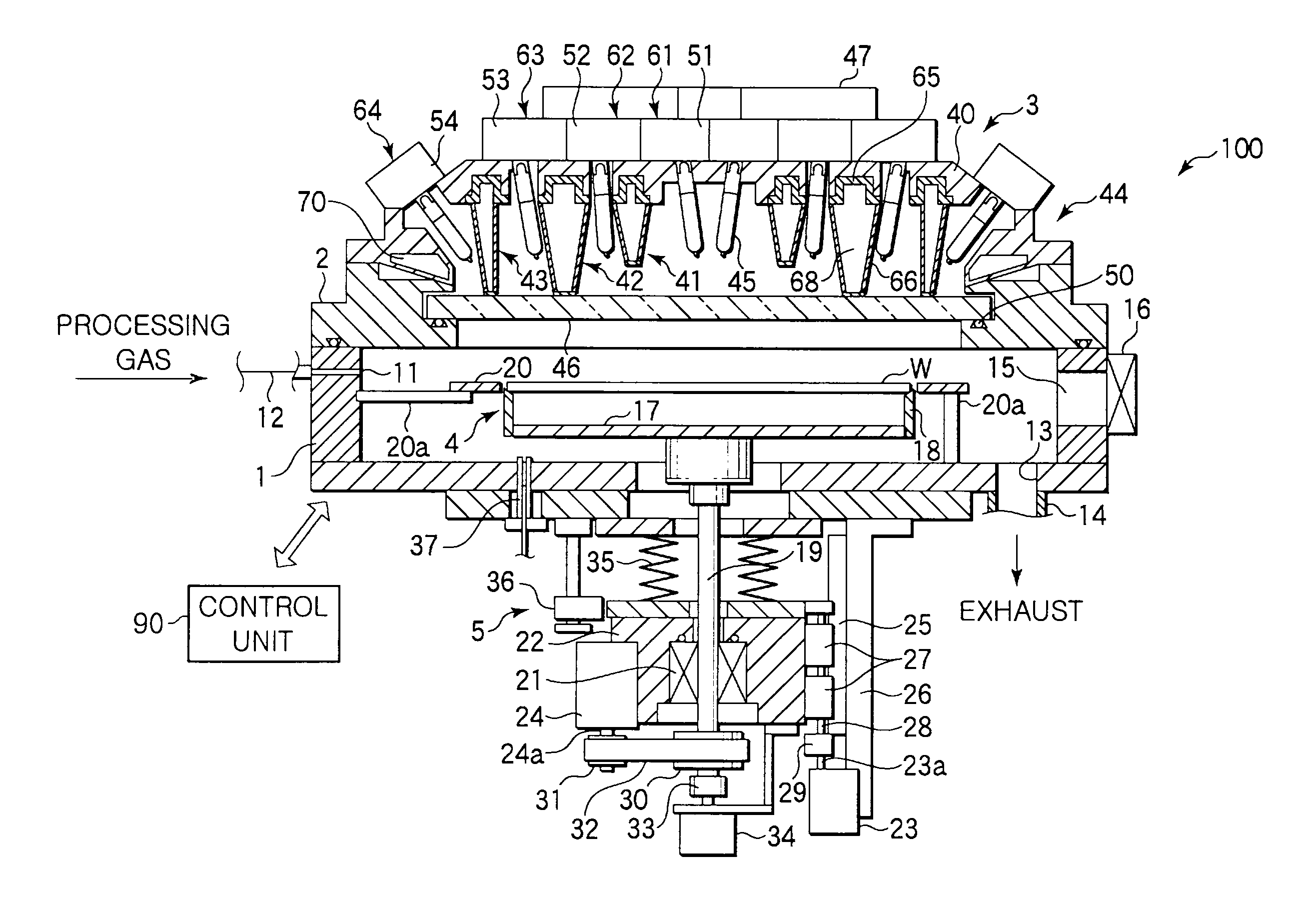
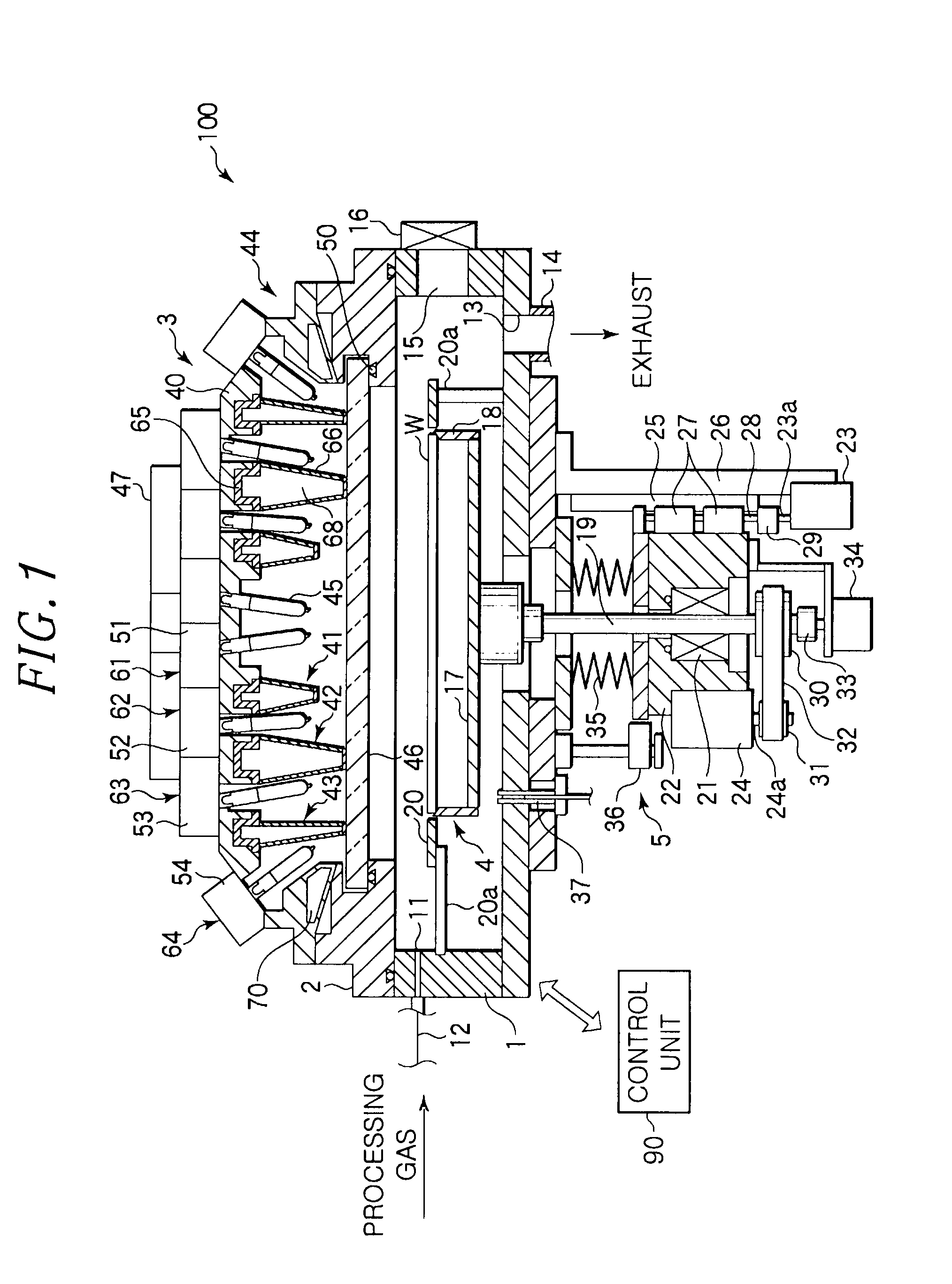
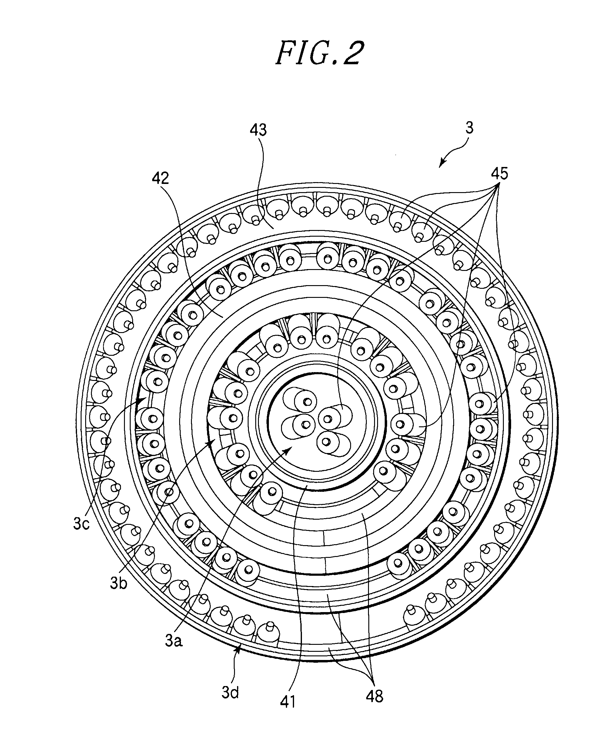
[0035]FIG. 1 is a cross sectional view showing an annealing apparatus as a heat treatment apparatus in accordance with a first embodiment of the present invention. F g. 2 is a bottom view showing a lamp unit thereof. FIG. 3 is a perspective view showing an exterior appearance of the lamp unit. FIG. 4 is a perspective view showing a state in which lamp modules are removed from the lamp unit. FIGS. 5A to 5D schematically show configurations of the lamp modules.

[0036]An annealing apparatus 100 mainly includes: a processing chamber 1 defining a processing space in which a wafer W as a target substrate is processed; a ring-shaped lid 2 fixed to an upper end of the processing chamber 1; a lamp unit 3, supported by the lid 2, having a plurality of halogen lamps; a wafer support 4 for supporting the wafer W in the processing chamber 1; and a driving unit 5 for raising, lowering and rotating the wafer W supported by the wafer support 4 in the processing chamber 1.

[0037]A gas inlet hole 11 is...

second embodiment

[0071]Hereinafter, a second embodiment of the present invention will be described.

[0072]The present embodiment is characterized in that the power supply terminals 57 of the halogen lamps 45 are protected. When the halogen lamps 45 are turned on during an annealing process, the power supply terminals 57 are heated by the heat thus produced at that time. When the temperatures of the power supply terminals 57 exceed about 350° C. by such heating, Mo foil used as a conductor is rapidly oxidized and short-circuited. Therefore, in the present embodiment, the power supply terminals 57 are cooled, and lights emitted from the halogen lamps 45 are prevented from reaching the power supply terminals 57.

[0073]FIG. 12 is a cross sectional view showing a part of a lamp unit 103 of an annealing apparatus 100 in accordance with the second embodiment of the present invention. FIG. 13 is a cross sectional view showing principal parts thereof. FIG. 14 is a perspective view showing an attachment state o...

third embodiment

[0083]Hereinafter, a third embodiment of the present invention will be described.

[0084]In the lamp unit, a seal between the light transmitting plate and the lid is positioned near the halogen lamps 45 and thus may be thermally deformed or fused by temperature increase caused by the heat generated from the halogen lamps in the lamp unit and the lights emitted from the halogen lamps. Thus, in the present embodiment, the configuration for protecting the seal will be mainly described.

[0085]FIG. 15 is a cross sectional view showing principal parts of an annealing apparatus in accordance with the third embodiment of the present invention. FIG. 16 is a cross sectional view showing a light transmitting plate supporting portion of the annealing apparatus in accordance with the third embodiment of the present invention. The annealing apparatus of the present embodiment includes a lamp unit 203 including a light transmitting plate 46′ having a flange portion (stepped portion) 46a. The flange p...


PUM


Abstract

A heat treatment apparatus is configured to include: a treatment chamber for accommodating therein a wafer; a substrate supporting unit for horizontally supporting the wafer in the treatment chamber; and a lamp unit provided above the treatment chamber. The lamp unit includes: a base member; a plurality of lamps provided on the lower surface of the base member whose front ends face downwardly; a plurality of ring-shaped reflectors concentrically provided on the lower surface of the base member to protrude downward; and a cooling head for supplying a cooling medium into the reflectors. At least some of the lamps are arranged along the reflectors, and cooling medium channels, each inner space of which is formed as a ring-shaped space, are respectively provided within the reflectors in the extending directions of the reflectors.

Description

FIELD OF THE INVENTION[0001]The present invention relates to a heat treatment apparatus capable of rapidly increasing and decreasing a temperature of a substrate.BACKGROUND OF THE INVENTION[0002]When a semiconductor device is manufactured, various heat treatments such as a film forming process, an oxidation / diffusion process, a modification process, an annealing process and the like are performed on a semiconductor wafer (hereinafter, simply referred to as a wafer) as a target substrate to be processed. Among the heat treatments, especially an annealing process for removing distortion after film formation or an annealing process after ion implantation requires a high-speed temperature control for raising or lowering the process temperature in order to improve a throughput and minimize diffusion. As for a heat treatment apparatus capable of performing a high-speed temperature control, an apparatus using a halogen lamp as a heating source is widely used.[0003]As for a heat treatment a...

Claims


Application Information

Patent Timeline
Patent Type & Authority Applications(United States)
IPC IPC(8): F27D11/00
CPCH01L21/68792H01L21/67115H01L21/205H01L21/26
Inventor KOMATSU, TOMOHITOKAMAISHI, TAKAYUKIYAMAZAKI, RYOJI
Owner TOKYO ELECTRON LTD
Why Eureka
Try Eureka