
Liquid crystal display device

Inactive Publication Date: 2012-06-14
OPTREX CORP
View PDF6 Cites 4 Cited by
  • Summary
  • Abstract
  • Description
  • Claims
  • Application Information

AI Technical Summary

Benefits of technology

[0012]Further, in the case of another mode liquid crystal display device such as a STN (Super Twisted Nematic) mode liquid crystal display device, a method for resolving electrostatic charge is known by adding an ionic impurity into liquid crystal to increase the electrical conductivity of the liquid crystal layer thereby to lower the after-mentioned panel specific resistance. Such a method for lowering the panel specific resistance is simple and will not increase the production cost of the product and thus is an effective method for resolving electrostatic charge of a liquid crystal display device.
[0014]The present invention has been made under these circumstances. That is, it is an object of the present invention to provide a vertical alignment type liquid crystal display device suitable for multiplex driving, which makes it possible to resolve the electrostatic charge problem and whereby inherent display irregularities can be reduced.
[0022]According to the present invention, it is possible to provide a vertical alignment type liquid crystal display device suitable for multiplex driving, which makes it possible to resolve electrostatic charge and whereby inherent display irregularities can be reduced.

Problems solved by technology

However, at present, the application is limited, and its use is also limited.
One of the reasons is a problem of inherent display irregularities during multiplex driving.
Such high frequency driving causes a restriction to the electrode resistance or to driving IC and has restricted the application range.
Further, the vertical alignment type liquid crystal display device usually has a problem such that the insulating property of the alignment film is high, it is easily electrostatically charged in an external electrostatic field to cause an abnormal display, and further such an abnormal display state is likely to prolong for a long time.
For example, if such a vertical alignment type liquid crystal display device is mounted on and assembled in an image display system of e.g. TV, it is likely to be abnormally lighted by static electricity during the assembling, thus leading to such a problem that it cannot be transferred to an inspection step for a long time until the abnormal lighting state is resolved.
However, there is a problem that such a method increases the production costs.
However, in the case of a vertical alignment type liquid crystal display device employing multiplex driving, it is known that an addition of an ionic impurity to the liquid crystal layer promotes the above-mentioned inherent display irregularities.
Thus, it has been considered difficult to practically employ such a simple method for resolving electrostatic charge in the case of a vertical alignment type liquid crystal display device employing multiplex driving.

Method used


Image

  • Liquid crystal display device
  • Liquid crystal display device
  • Liquid crystal display device

Examples


example 1

[0132]The above liquid crystal 2 was applied to the vertical alignment type liquid crystal display device capable of multiplex driving in this embodiment as described above, whereby a liquid crystal display device of Example 1 was prepared. The electrode structure of a pixel of the liquid crystal display device of Example 1 was made to be the same as the first example of the second electrode form applicable to the vertical alignment type liquid crystal display device in this embodiment, as shown in FIG. 10. In such a case, the size of one pixel was 0.39 mm square, the pitch for forming sub-pixels was 80 μm, and each linear slit width was made to be 10 μm. The panel specific resistance was 4.6×10¹⁰ Ωcm. Using the vertical alignment type liquid crystal display device of Example 1, static electricity was applied to the substrate surface for displaying the liquid crystal layer, whereby the time until electrostatic charge was resolved, was 5 seconds and thus was found to be a very short ...

example 2

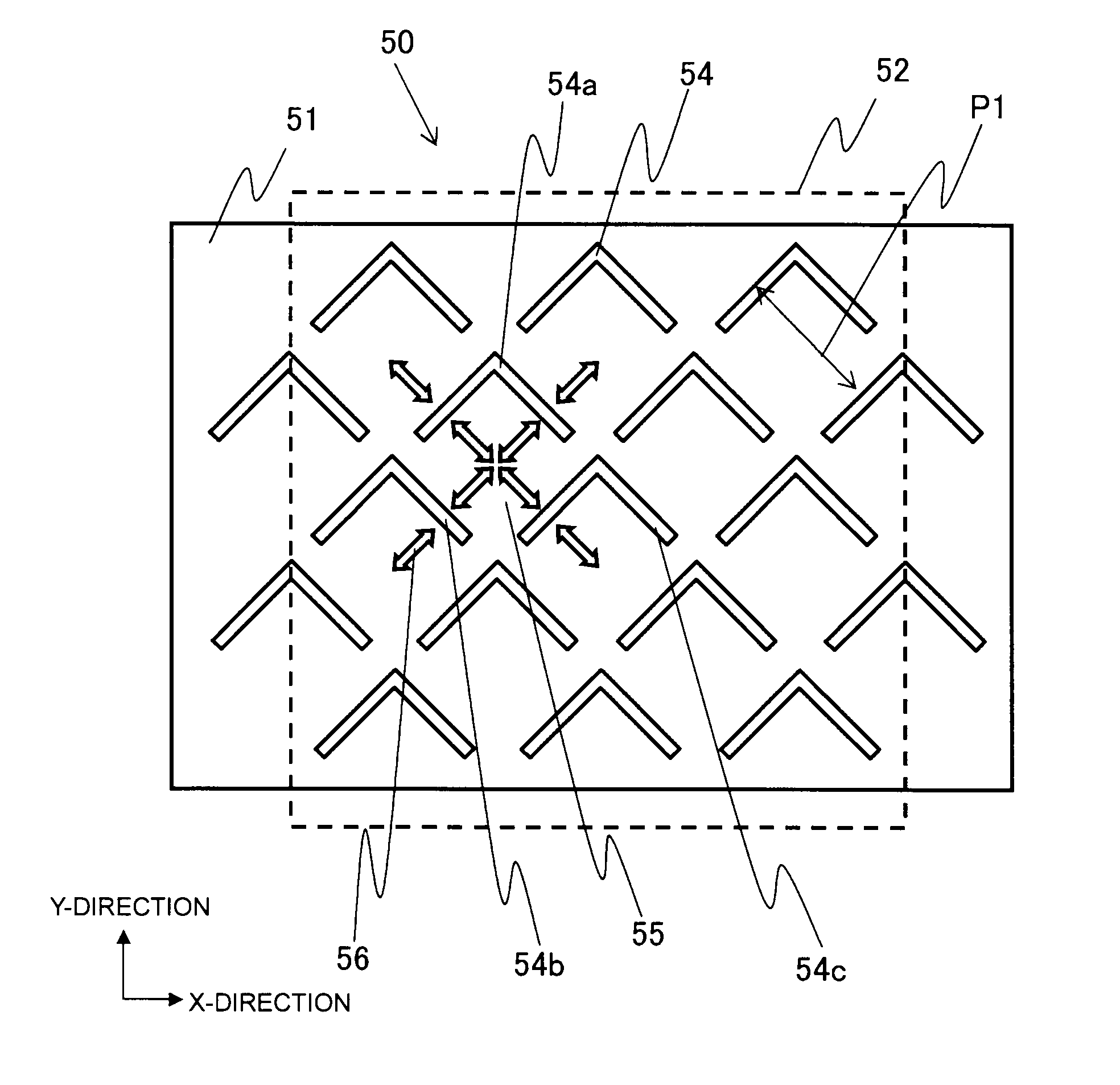
[0135]The above liquid crystal 2 was applied to the vertical alignment type liquid crystal display device capable of multiplex driving in this embodiment as described above, whereby a liquid crystal display device of Example 2 was prepared. The electrode structure of a pixel in the liquid crystal display device of Example 2 was made to be the same as the first example of the first electrode form applicable to the vertical alignment type liquid crystal display device in this embodiment as shown in FIG. 6. In such a case, the size of one pixel was 0.39 mm square, the pitch for forming sub-pixels was 80 μm, and the width of a linearly extending slit portion of a bent slit was 10 μm. The panel specific resistance was 4.6×10¹⁰ Ωcm.

[0136]Using the vertical alignment type liquid crystal display device of Example 2, static electricity was applied to the substrate surface for displaying the liquid crystal layer, whereby the time until the electrostatic charge was resolved, was 4 seconds and ...

example 3

[0139]The above liquid crystal 2 was applied to the vertical alignment type liquid crystal display device capable of multiplex driving in this embodiment as described above, whereby a liquid crystal display device of Example 3 was prepared. The electrode structure of a pixel in the liquid crystal display device of Example 3 was made to be the same as the second example of the second electrode form applicable to the vertical alignment type liquid crystal display device in this embodiment as shown in FIG. 11. In such a case, the size of one pixel was 0.39 mm square, the pitch for forming sub-pixels was 80 μm, and the width of a linear slit was 10 μm. The panel specific resistance was 4.6×10¹⁰ Ωcm.

[0140]By using the vertical alignment type liquid crystal display device of Example 3, static electricity was applied to the substrate surface for displaying the liquid crystal layer, whereby the time until the electrostatic charge was resolved, was 5 seconds and thus was found to be a very s...


PUM


Abstract

A vertical alignment type liquid crystal display, having a specific resistance within a range of from 1×10¹⁰ Ωcm to 2×10¹¹ Ωcm, and containing a liquid crystal layer sandwiched by a substrate having a front electrode on the surface and a substrate having a back electrode, wherein the liquid crystal layer is aligned perpendicular to the electrode surface when no voltage is applied, and upon application of a voltage by multiplex driving, the liquid crystal layer in pixels undergoes an alignment change to align parallel to the substrates. By using slits as pixel dividing structures provided on the front of the electrode, one pixel is divided into a plurality of sub-pixels, such that the directions of the alignment change upon application of a voltage are different between adjacent sub-pixels interposing the slits, and the sub-pixels are formed within a range of from 50 μm to 100 μm.

Description

BACKGROUND OF THE INVENTION[0001]1. Field of the Invention[0002]The present invention relates to a liquid crystal display device.[0003]2. Discussion of Background[0004]A liquid crystal display device is constructed by sandwiching a liquid crystal layer between a transparent substrate disposed on a viewer's side and a transparent substrate disposed on the opposite side to the viewer against such a transparent substrate. The liquid crystal layer is made of e.g. nematic phase liquid crystal (hereinafter referred to also as nematic liquid crystal). On the inner surface of each substrate, a patterned transparent electrode made of e.g. ITO (Indium Tin Oxide) is formed. Between the electrode on each substrate and the liquid crystal layer, an alignment film is formed as a liquid crystal alignment layer to realize a uniform initial alignment of liquid crystal. And, depending upon an electric filed to be applied between the electrodes, the liquid crystal layer undergoes an alignment change fr...

Claims


Application Information

Patent Timeline
IPC IPC(8): G02F1/1343G02F1/1335
CPCG02F1/133707G02F1/134309G02F2001/134345G02F2001/133742G02F1/1395G02F1/133742G02F1/134345
Inventor NAKAGAWA, YUTAKASODA, YUJIHARADA, KORETOMO
Owner OPTREX CORP
Learn More