Power-supply device, and LED lighting equipment and hard disk drive using the same
- Summary
- Abstract
- Description
- Claims
- Application Information
AI Technical Summary
Benefits of technology
Problems solved by technology
Method used
Image

Examples
first embodiment
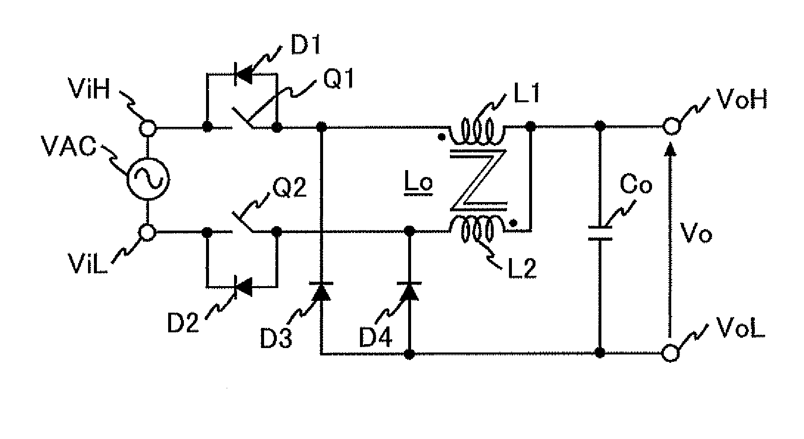
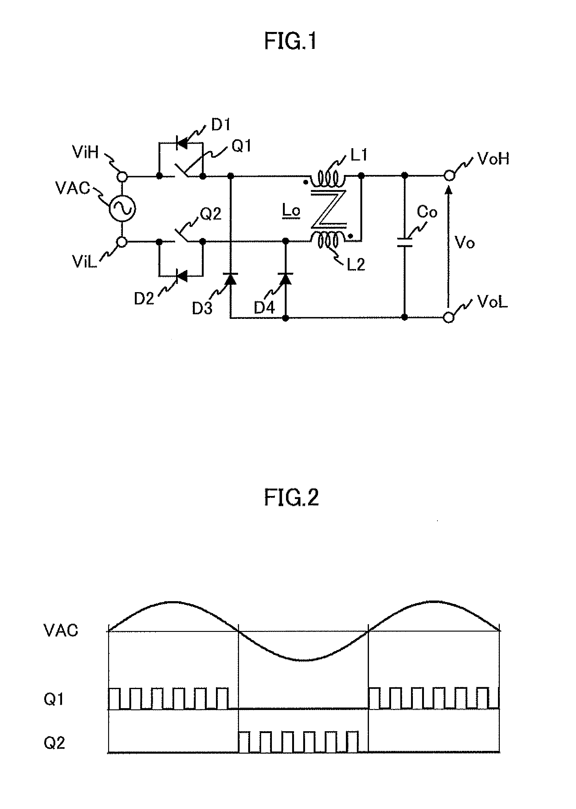
[0027]The first embodiment of the present invention will be explained. FIG. 1 is a circuit diagram showing a configuration of the power-supply device according to the first embodiment of the present invention. As illustrated in FIG. 1, both ViH and ViL show input terminals, and both VoH (a High side) and VoL (a Low side) show output terminals.
[0028]The input terminal ViH is connected to a cathode of a diode D3 and one end of an inductor L1 (a side of black circle mark: FIG. 1), via a switch Q1.
[0029]The other end of the input terminal ViL is connected to a cathode of a diode D4 and one end of an inductor L2 (a counter side of a black circle mark: FIG. 1), through the switch Q2.
[0030]Further, the output terminal VoH is connected to one end of an output capacitor Co (a positive polarity side: the polarity is not shown), the other end of the inductor L1 (a counter side of a black circle mark: FIG. 1), and the other end of the inductor L2.
[0031]The other end of the output terminal VoL i...
second embodiment
[0080]FIG. 5 shows the second embodiment of the power-supply device to which the present invention is applied. The second embodiment is different from the first embodiment of FIG. 1 in that the switch Q2 is, in a direction shown in FIG. 5, connected in series with the switch Q1. Except for the switch Q2, an explanation will be skipped as it is the same in FIG. 1.
[0081]In FIG. 5, during the positive half cycle period of the AC input voltage VAC, the positive voltage is input from the input terminal ViH by the ON / OFF operation of the switch Q1, and the diode D2 operates in a forward direction.
[0082]Therefore, the energy supplied from the input terminal ViH flows through the path of the input terminal ViH, the switch Q1, the diode D2, the inductor L1, the output capacitor Co, the diode D4, and the input terminal ViL. Consequently, the operation and the function of the first buck converter become similar to the ON / OFF operation of the switch Q1 in FIG. 1.
[0083]Furthermore, during the ne...
third embodiment
[0086]FIG. 6 is a circuit diagram showing the configuration of the third embodiment of the power-supply device of the present invention.
[0087]FIG. 6 is different from FIG. 1 in that the switch Q1 and the switch Q2 are arrayed alternately, and connected in parallel.
[0088]Comparing FIG. 6 with FIG. 1 or FIG. 5, the switch Q1 and the switch Q2 are substituted by reverse blocking TGBT (insulated Gate Bipolar Transistor), and the diode D1 and the diode D2 are removed. The other part of the circuit in FIG. 6 is the same as FIG. 1 or FIG. 5. Therefore, an explanation except to the switch Q1 and the switch Q2 will be skipped.
[0089]In FIG. 6, during the positive half cycle period of the AC input voltage VAC, the energy supplied from the input terminal ViH flows through the path of the input terminal ViH, the switch Q1, the inductor L1, the output capacitor Co, the diode D4, and the input terminal ViL by the ON / OFF operation of the switch Q1. The operation and the function of the first buck c...
PUM
 Abstract
Description
Claims
Application Information
 - R&D
- Intellectual Property
- Life Sciences
- Materials
- Tech Scout
- Unparalleled Data Quality
- Higher Quality Content
- 60% Fewer Hallucinations
Browse by: Latest US Patents, China's latest patents, Technical Efficacy Thesaurus, Application Domain, Technology Topic, Popular Technical Reports.
© 2025 PatSnap. All rights reserved.Legal|Privacy policy|Modern Slavery Act Transparency Statement|Sitemap|About US| Contact US: help@patsnap.com