
Solid electrolytic capacitor and method for manufacturing the same

Active Publication Date: 2012-06-14
SANYO ELECTRIC CO LTD
View PDF1 Cites 1 Cited by
  • Summary
  • Abstract
  • Description
  • Claims
  • Application Information

AI Technical Summary

Benefits of technology

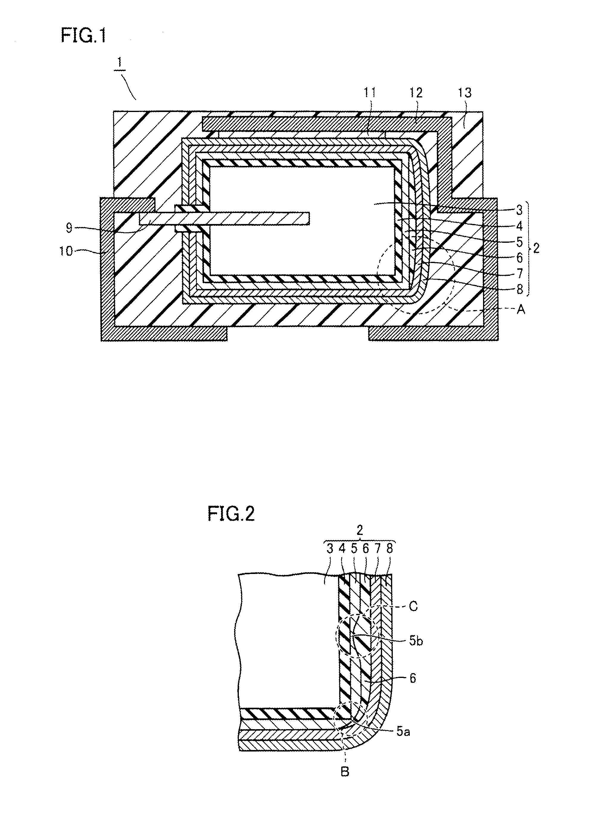
[0011]In the solid electrolytic capacitor according to the present invention, the insulating layer is formed to cover the relatively thin portion of the solid electrolyte layer in the solid electrolyte layer. Therefore, an electrical short circuit between the anode body and the cathode layer can be suppressed. As a result, the reliability of the solid electrolytic capacitor can be increased.
[0012]In the method for manufacturing the solid electrolytic capacitor according to the present invention, the insulating layer is formed to cover the relatively thin portion of the solid electrolyte layer, which was formed due to formation of the solid electrolyte layer. Therefore, an electrical short circuit between the anode body and the cathode layer can be suppressed. As a result, the reliability of the solid electrolytic capacitor can be increased.

Problems solved by technology

It has been found, however, that this method for forming the solid electrolyte layer (polymerization) and the shape of the anode body may make it difficult in some cases to form the solid electrolyte layer having an uniform thickness on a surface of the dielectric coating.

Method used


Image

  • Solid electrolytic capacitor and method for manufacturing the same
  • Solid electrolytic capacitor and method for manufacturing the same
  • Solid electrolytic capacitor and method for manufacturing the same

Examples


first embodiment

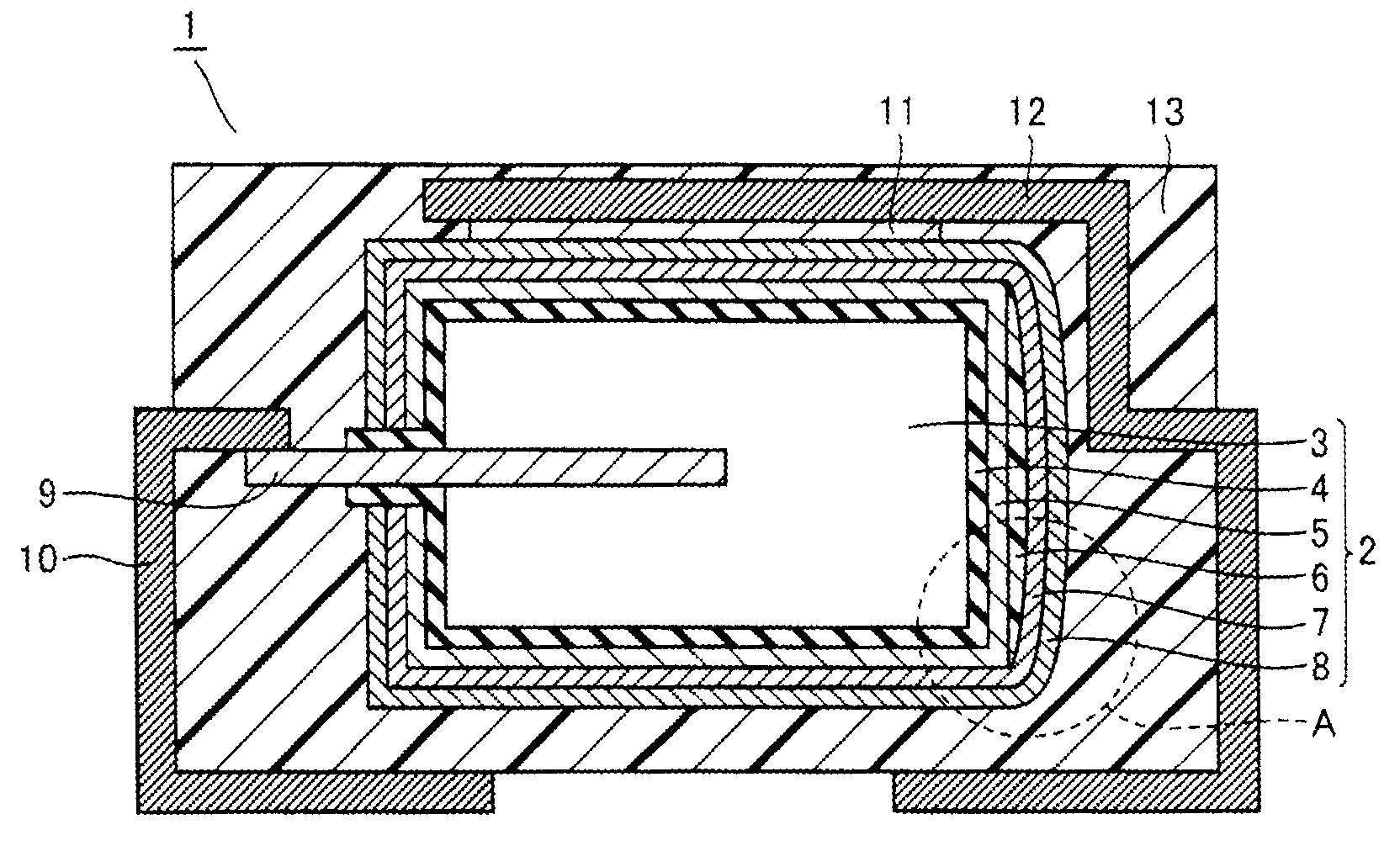
[0021]A description will be given to a solid electrolytic capacitor according to a first embodiment of the present invention. As shown in FIG. 1, a capacitor element 2 serving as a capacitor main body in a solid electrolytic capacitor 1 includes an anode body 3 serving as an anode, a dielectric coating 4, a solid electrolyte layer 5, an insulating layer 6, and a carbon layer 7 and a silver paste layer 8 serving as a cathode.

[0022]Anode body 3 of capacitor element 2 has an anode lead 9 provided in an upright manner and one end of an anode terminal 10 is electrically connected to anode lead 9. One end side of a cathode terminal 12 is electrically connected to silver paste layer 8 of capacitor element 2 with a conductive bonding layer 11 interposed therebetween. An exterior resin 13 seals capacitor element 2 in such a manner that the other end side of anode terminal 10 and the other end side of cathode terminal 12 are exposed.

[0023]Next, a structure of capacitor element 2 will be descr...

second embodiment

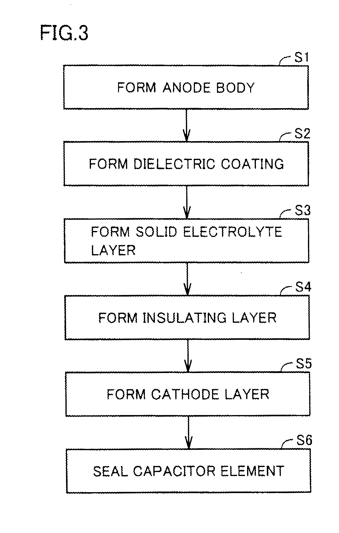
[0028]A description will be given to one example of a method for manufacturing the above-mentioned solid electrolytic capacitor as a second embodiment of the present invention. FIG. 3 shows one example of a manufacturing flow. As shown in FIGS. 3 and 1, an anode body is first formed in step S1. Metal powder having the valve action is prepared, and this metal powder is molded into a desired shape, with one end side of anode lead 9 in the longitudinal direction buried into the metal powder. Next, the molded body is sintered to form anode body 3. This anode body 3 may be porous.

[0029]Next, a dielectric coating is formed in step S2. Anode body 3 is subjected to chemical conversion treatment, and thereby dielectric coating 4 is formed to cover anode body 3. As the chemical conversion treatment, there is a method for soaking anode body 3 in a chemical conversion solution such as a phosphoric acid aqueous solution or nitric acid aqueous solution, and applying a predetermined voltage, for e...


PUM

PropertyMeasurementUnit
Shapeaaaaaaaaaa
aaaaaaaaaa

Abstract

A capacitor element of a solid electrolytic capacitor includes an anode body serving as an anode, a dielectric coating, a solid electrolyte layer, an insulating layer, and a carbon layer and a silver paste layer serving as a cathode. The insulating layer is formed to cover a relatively thin portion of the solid electrolyte layer.

Description

[0001]This nonprovisional application is based on Japanese Patent Application No. 2010-277994 filed on Dec. 14, 2010 with the Japan Patent Office, the entire contents of which are hereby incorporated by reference.BACKGROUND OF THE INVENTION[0002]1. Field of the Invention[0003]The present invention relates to a solid electrolytic capacitor and a method for manufacturing the same, and particularly to a solid electrolytic capacitor including an anode body formed of a sintered compact, and a method for manufacturing such solid electrolytic capacitor.[0004]2. Description of the Related Art[0005]A solid electrolytic capacitor has been conventionally known as a capacitor suitable for size reduction. This solid electrolytic capacitor is manufactured as follows. First, valve metal powder such as, for example, tantalum (Ta) is molded into a molded body having a predetermined shape and the molded body is sintered, thereby forming an anode body. Next, a surface of the anode body is subjected to...

Claims


Application Information

Patent Timeline
IPC IPC(8): H01G9/004H01G9/15
CPCH01G9/0036H01G9/028Y10T29/417H01G9/15H01G9/0425
Inventor UEDA, MASAHIRO
Owner SANYO ELECTRIC CO LTD
Learn More