System and method providing over current protection based on duty cycle information for power converter

a technology of duty cycle information and power converter, which is applied in the direction of electric variable regulation, process and machine control, instruments, etc., can solve the problems of limited current flowing through the power switch and transformer winding, current can reach a level at which damage to the power switch is imminent, and the rectifier components on the transformer secondary side are subject to permanent damage, so as to achieve a broader range of applicability

Active Publication Date: 2012-06-14
ON BRIGHT ELECTRONICS SHANGHAI
View PDF10 Cites 119 Cited by
  • Summary
  • Abstract
  • Description
  • Claims
  • Application Information

AI Technical Summary

Benefits of technology

[0003]The present invention is directed to integrated circuits. More particularly, the invention provides a control system and method for over-current protection and over-power p

Problems solved by technology

The current flowing through the power switch and transformer winding may be limited by an OCP system.
If the OCP system is not effective, the current can reach a level at which damage to the power switch is imminent due to excessive current and voltage stress at switching or thermal run-away during operation.
Consequently, the rectifier components on the transformer secondary side are subject to permanent damage due to excessive voltage and current stress in many offline flyback converters.
This limitatio

Method used


Image

  • System and method providing over current protection based on duty cycle information for power converter
  • System and method providing over current protection based on duty cycle information for power converter
  • System and method providing over current protection based on duty cycle information for power converter

Examples


Embodiment Construction

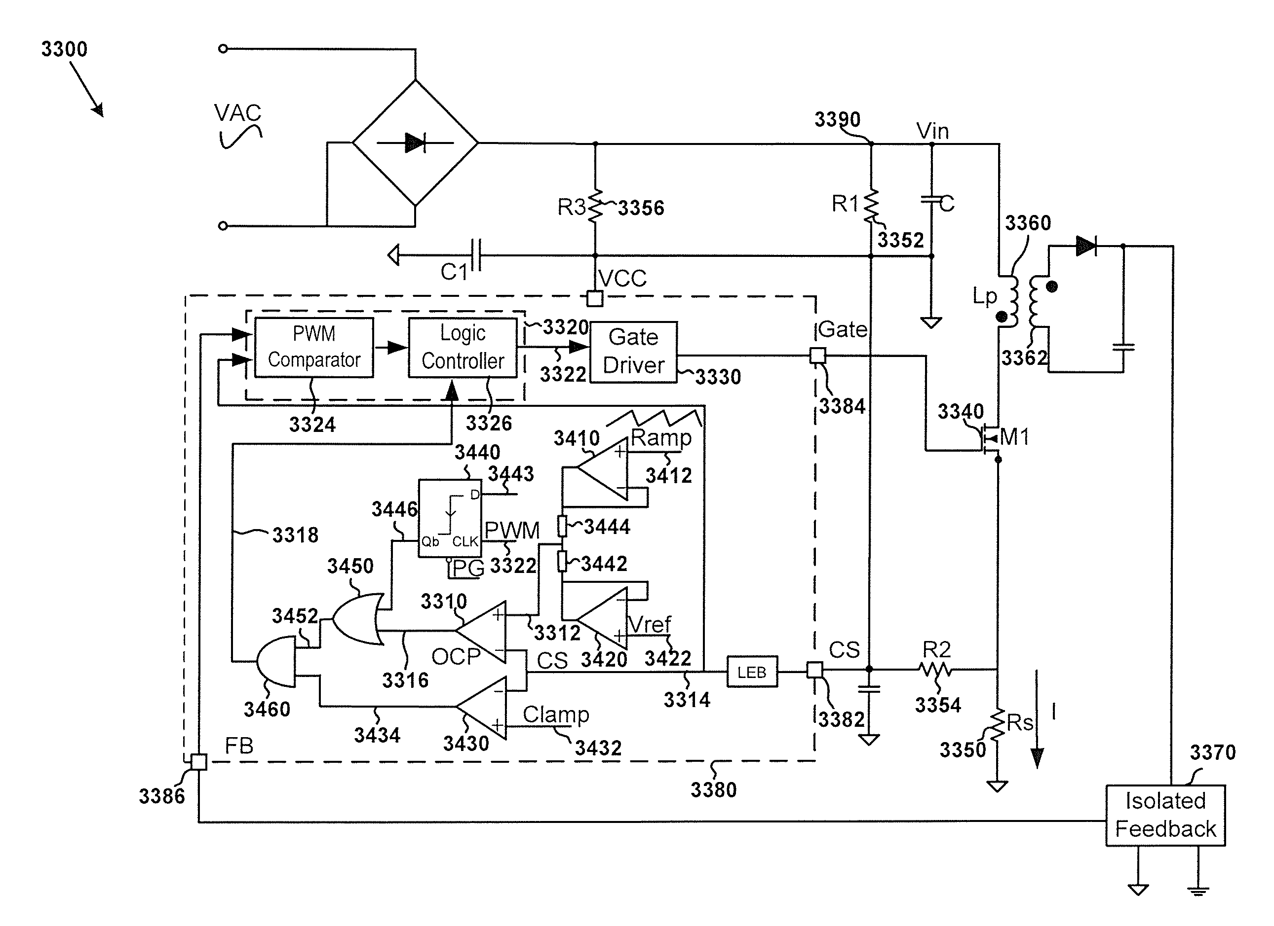
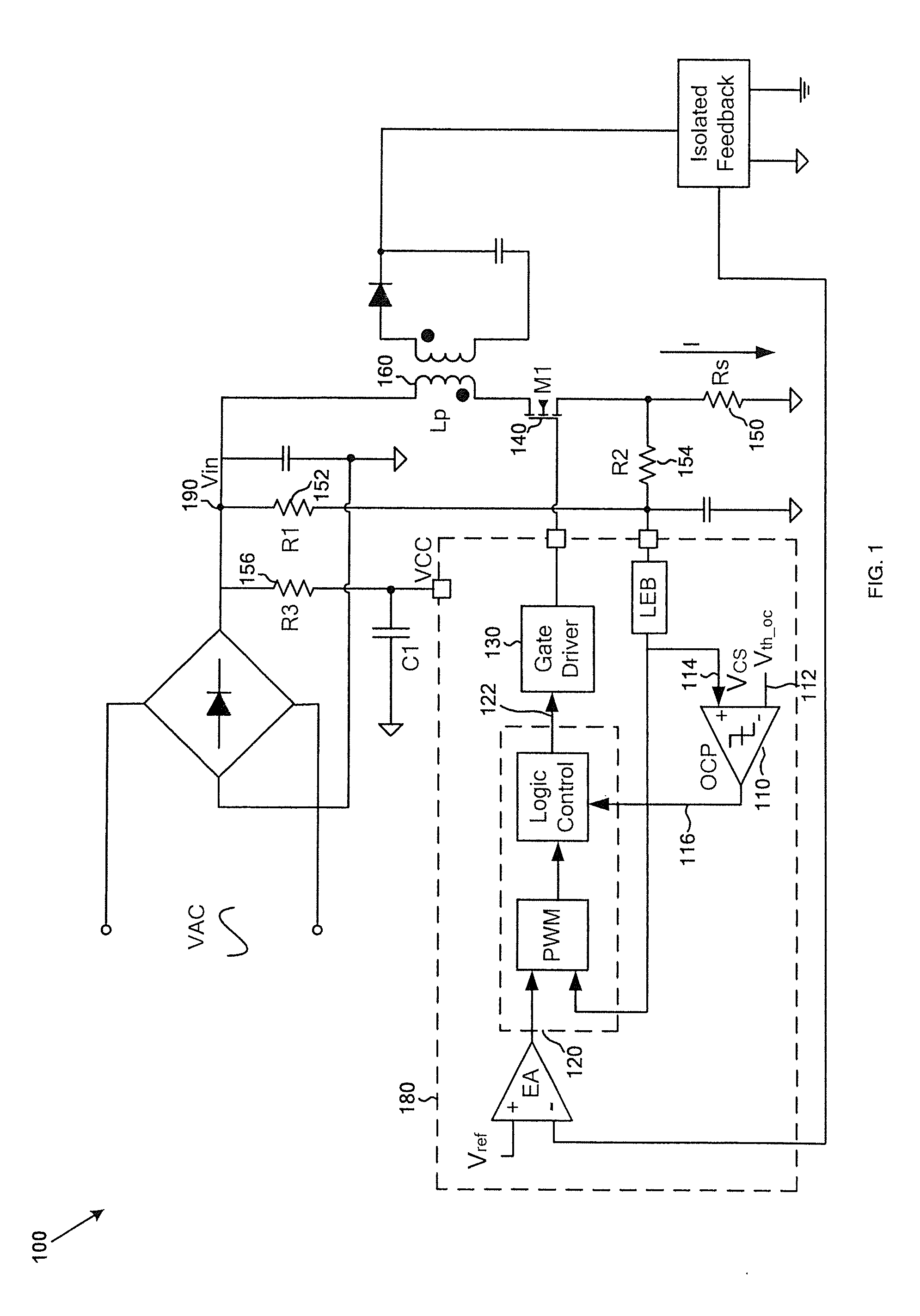
[0056]The present invention is directed to integrated circuits. More particularly, the invention provides a control system and method for over-current protection and over-power protection. Merely by way of example, the invention has been applied to a power converter. But it would be recognized that the invention has a much broader range of applicability.

[0057]FIGS. 8 and 9 are simplified timing diagrams for a switch-mode converter corresponding to different line input voltages in the CCM mode. For example, the line input voltage for FIG. 8 is higher than the line input voltage for FIG. 9.

[0058]As shown in FIG. 8, curves 2810, 2820, 2830, and 2840 represent the timing diagrams for a clock signal, a PWM signal, an over-current threshold signal, and a current sensing signal respectively. For example, the clock signal is in sync with the PWM signal. In another example, the PWM signal is generated by a PWM controller component. In yet another example, the over-current threshold signal is...


PUM


Abstract

System and method for protecting a power converter. The system includes a duty-cycle detection component configured to receive a modulation signal, determine a first duty cycle corresponding to a first period of the modulation signal, compare the first duty cycle with a threshold duty cycle, and generate a duty-cycle comparison signal. Additionally, the system includes a threshold generator configured to receive the duty-cycle comparison signal and generate a threshold signal corresponding to a second period of the modulation signal, the second period being after the first period, and a comparator configured to receive the threshold signal and a first signal and to generate a first comparison signal. The first signal is associated with an input current for a power converter. Moreover, the system includes a pulse-width-modulation component configured to receive the first comparison signal and generate the modulation signal for adjusting the input current for the power converter.

Description

1. CROSS-REFERENCES TO RELATED APPLICATIONS[0001]This application claims priority to Chinese Patent Application No. 201010587658.9, filed Dec. 8, 2010, commonly assigned, incorporated by reference herein for all purposes.[0002]Additionally, this application is related to U.S. patent application Ser. Nos. 11 / 213,657, 12 / 125,033, 11 / 752,926, and 12 / 690,808, commonly assigned, incorporated by reference herein for all purposes.2. BACKGROUND OF THE INVENTION[0003]The present invention is directed to integrated circuits. More particularly, the invention provides a control system and method for over-current protection and over-power protection. Merely by way of example, the invention has been applied to a power converter. But it would be recognized that the invention has a much broader range of applicability.[0004]Power converters are widely used for consumer electronics such as portable devices. The power converters can convert electric power from one form to another form. As an example, ...

Claims


Application Information

Patent Timeline
IPC IPC(8): H02M3/335
CPCH02H3/006H02M3/33507H02M1/32
Inventor CAO, YAMINGDONG, JINYAZHANG, YUNCHAOFANG, LIEYI
Owner ON BRIGHT ELECTRONICS SHANGHAI
Why Eureka
Try Eureka