
Nuclear reactor internal hydraulic control rod drive mechanism assembly

a technology of drive mechanism and nuclear reactor, which is applied in the direction of nuclear reaction control, greenhouse gas reduction, climate sustainability, etc., can solve the problems of increasing the rate of nuclear reaction and core power output, reducing the extent of neutron absorption, and unable to reliably operate conventional arrangement of coils

Active Publication Date: 2012-06-14
WESTINGHOUSE ELECTRIC CORP
View PDF11 Cites 5 Cited by
  • Summary
  • Abstract
  • Description
  • Claims
  • Application Information

AI Technical Summary

Benefits of technology

[0019]In another embodiment, the control rod is a shutdown rod moveable, substantially in a single step, into or out of the reactor. In still another embodiment, the drive mechanism moves the control rod in discrete increments into and out of the core wherein the discrete increments are greater than ⅝ inch (1.63 cm) and less than or equal to two inches (5.08 cm). Preferably, the discrete increments are greater than ⅝ inch (1.63 cm) and less than or equal to one inch (2.54 cm).
[0020]Desirably, the hydraulic piston has a vent that is vented directly into the coolant exiting the reactor core. Preferably, the drive mechanism has a lift capacity of greater than 360 pounds (163.29 Kg) and less than or equal to 1,000 pounds (453.59 Kg).

Problems solved by technology

Inserting a control rod further into the core causes more neutrons to be absorbed without contributing to fission in an adjacent fuel rod; and retracting the control rod reduces the extent of neutron absorption and increases the rate of the nuclear reaction and the power output of the core.
In such an arrangement, the entire control rod drive mechanism is immersed within the reactor coolant, in which the conventional arrangement of coils could not operate reliably.
Even if the coils were housed to protect them from direct contact with the coolant, conventional coils could not withstand the temperatures they would experience in an operating cycle.
actor. From the foregoing, it should be apparent that a traditional magnetic jack control rod drive system would not function reliably in the reactor design illustrated in FIGS. 2 and 3, because the coils would be fully immersed in the coolant, and even if shielded from the coolant with an outer housing, would not readily receive sufficient cooling to prevent failures of the magnetic

Method used


Image

  • Nuclear reactor internal hydraulic control rod drive mechanism assembly
  • Nuclear reactor internal hydraulic control rod drive mechanism assembly
  • Nuclear reactor internal hydraulic control rod drive mechanism assembly

Examples


Embodiment Construction

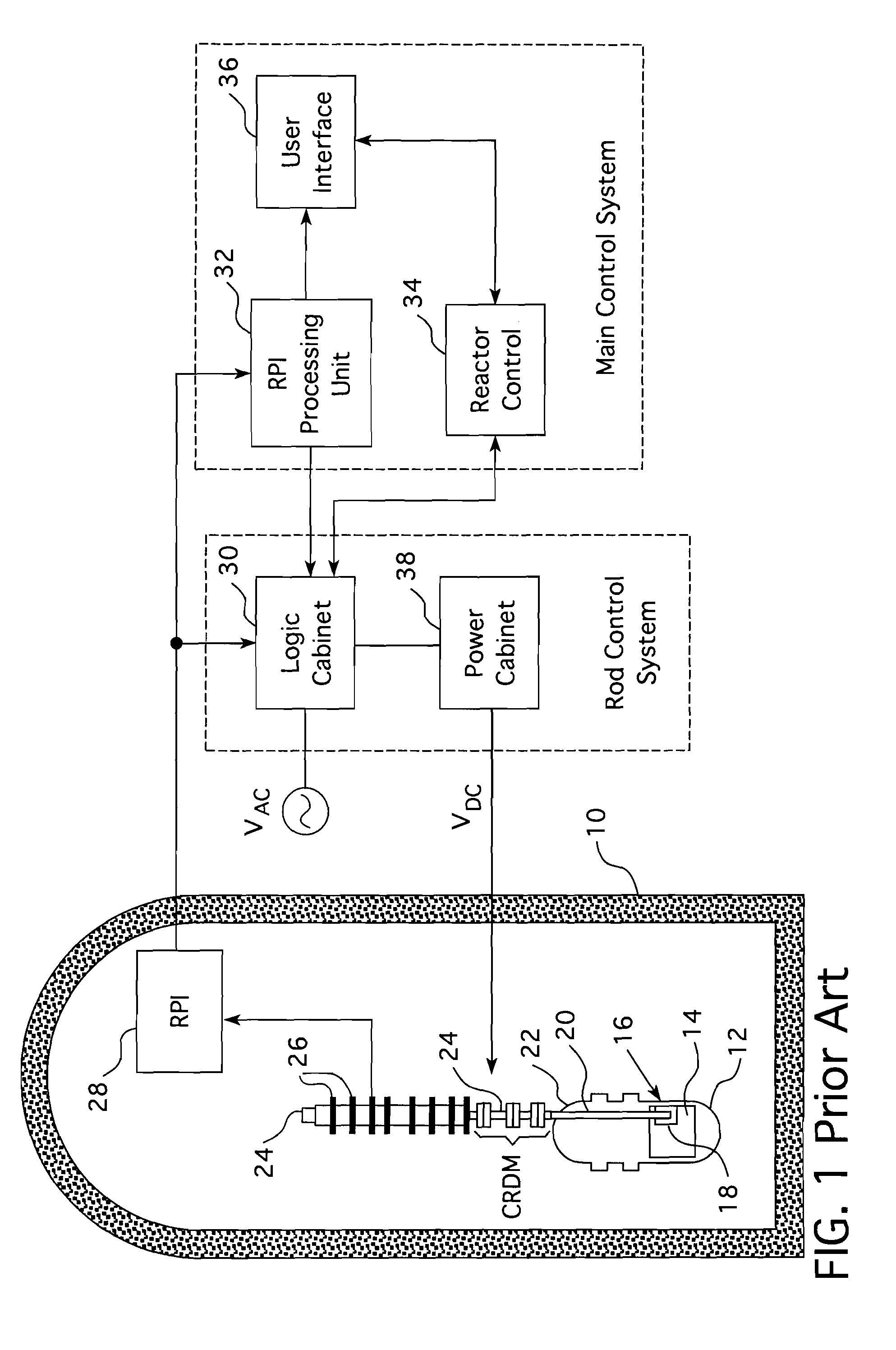
[0031]As stated in regard to FIG. 1, the control rods are attached in clusters 16, commonly referred to as spider assemblies, with each cluster being commonly driven by a drive rod 20 disposed in a vertical support housing 24 above the reactor core 14 containing the fuel assemblies into which the control rods 18 are advanced or from which the control rods are retracted for variable damping of nuclear flux within the reactor core. The moving parts of the control rod drive mechanism are within the pressure envelope of the reactor and in the conventional designs, the electromagnetic coils (CRDM) for driving the moveable parts are disposed around and about each of the housings 24 that extends above the reactor. In viewing the several figures, it should be appreciated that like reference characters refer to corresponding parts.

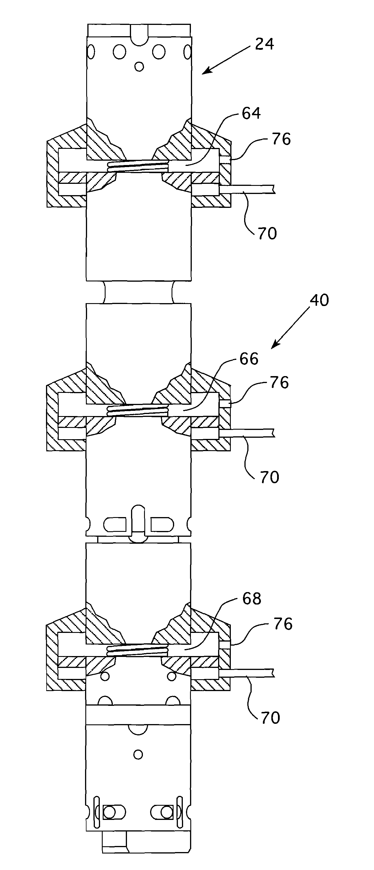
[0032]FIG. 4 shows a drive rod drive mechanism 40 with the extended portion of the housing 24 of a traditional reactor partly cut away to show the grippers 42 and ...


PUM


Abstract

A control rod drive system for a nuclear reactor that employs hydraulic cylinders to operate a conventional plunger / gripper drive system to incrementally move control rods into and out of the core of a reactor. The pressure differential for driving hydraulic pistons within the cylinders is obtained from the difference in pressure between the outside and inside of the core barrel of the reactor and control of the pistons is obtained from external solenoids attached to the reactor control system. The external solenoids regulate a charging pump feed to Poppet valves that control the hydraulic feed to the cylinders. A hydraulic piston / cylinder drive is also provided for the shutdown rods which operate in either an all in or out of the core condition.

Description

CROSS REFERENCE TO RELATED APPLICATION[0001]This application claims priority under 35 U.S.C. §119(e) to U.S. Provisional Patent Application Ser. No. 61 / 421,247, filed Dec. 9, 2010 entitled, INTERNAL HYDRAULIC CRDM ASSEMBLY.BACKGROUND[0002]1. Field[0003]This invention relates in general to nuclear reactor control systems, and, in particular to systems for controlling the movement of nuclear control rods into and out of the core of the nuclear reactor.[0004]2. Description of Related Art[0005]In a nuclear reactor for power generation, such as a pressurized water reactor, heat is generated by fission of a nuclear fuel such enriched uranium, and transferred into a coolant flowing through a reactor core. The core contains elongated nuclear fuel rods mounted in proximity with one another in a fuel assembly structure, through and over which the coolant flows. The fuel rods are spaced from one another in co-extensive parallel arrays. Some of the neutrons and other atomic particles released d...

Claims


Application Information

Patent Timeline
Patent Type & Authority Applications(United States)
IPC IPC(8): G21C7/16
CPCG21C7/16Y02E30/39H02K33/00Y02E30/30G21C7/08
Inventor ALLEN, BRUCE F.FALVO, GREGORY E.HARKNESS, ALEXANDER W.
Owner WESTINGHOUSE ELECTRIC CORP
Features
  • Generate Ideas
  • Intellectual Property
  • Life Sciences
  • Materials
  • Tech Scout
  • Unparalleled Data Quality
  • Higher Quality Content
  • 60% Fewer Hallucinations
Learn More