Distributed antenna system, base station device, and antenna selection control method

Inactive Publication Date: 2012-06-14
HITACHI LTD
View PDF3 Cites 65 Cited by
  • Summary
  • Abstract
  • Description
  • Claims
  • Application Information

AI Technical Summary

Benefits of technology

[0053]It is possible, by the present invention, to provide a technique in which a communication system such as the MIMO communication, the SISO communication, or the SIMO communication can be optimally selected according to the traffic volume of the terminal, the consumption of the radio resource attributable to feedback of the PMI information can be saved as compared with a case in which a communication always using the plural antennas such as the MIMO communication is conducted, and/or an effective radio communication can be realized.
[0054]It is possible, by the present invention, to provide a technique in which a terminal that conducts a communication using one antenna for transmission or reception such as the SISO communication or the SIMO communication is selected to provide a signal throughput required according to the traffic, and the power consumption of the terminal can be reduced as compared to a case in which a communication always using the plural antennas such as the MIMO communication is conducted.
[0055]Still, It is possi

Problems solved by technology

Because the antennas other than the MIMO communication antenna cause interference, it is conceivable that the other antennas are not used.
However, if, for example, two antennas are selected in the MIMO comm

Method used


Image

  • Distributed antenna system, base station device, and antenna selection control method
  • Distributed antenna system, base station device, and antenna selection control method
  • Distributed antenna system, base station device, and antenna selection control method

Examples


Example

A. FIRST EMBODIMENT

1. System Configuration

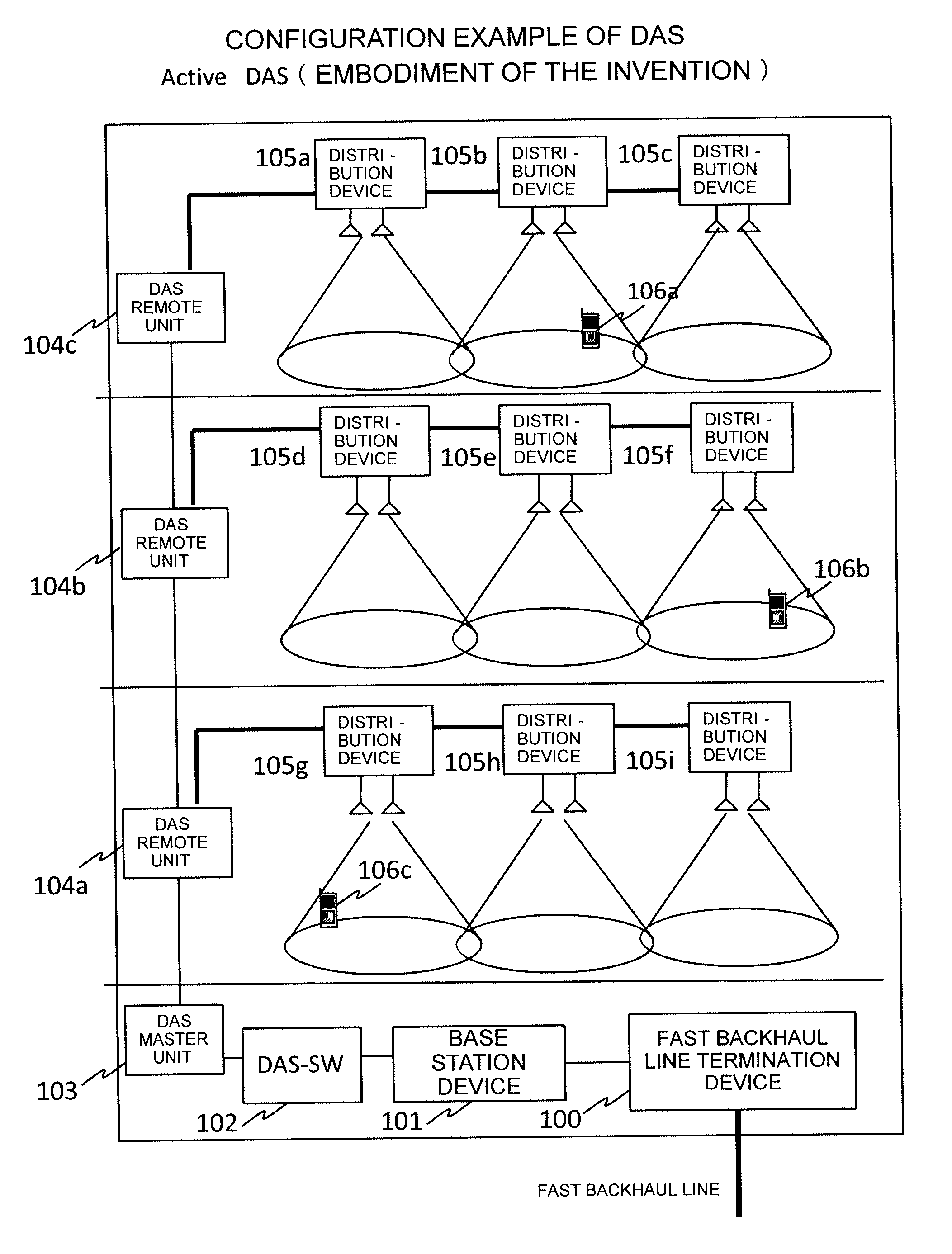
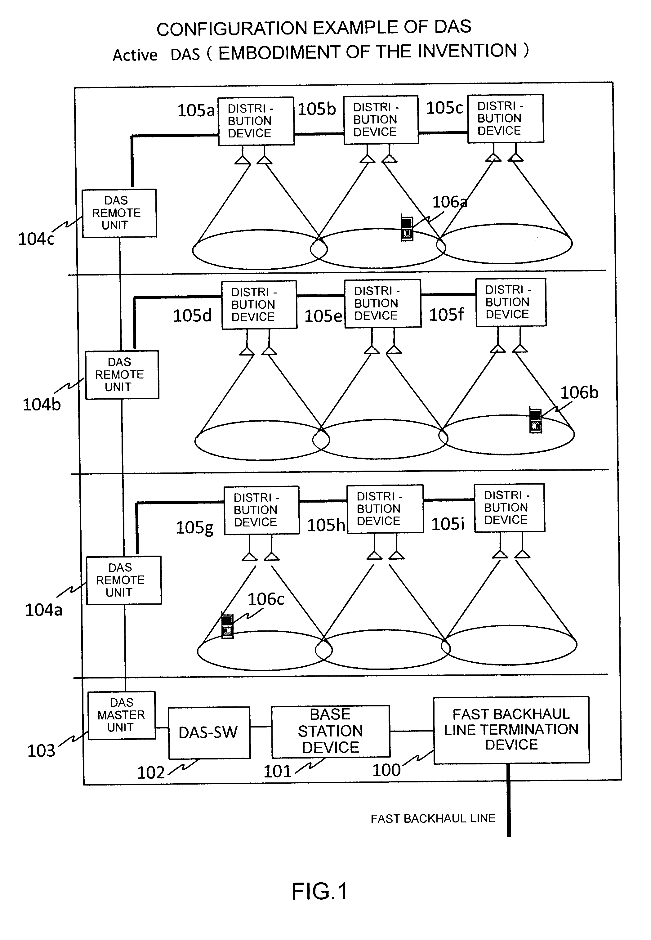
[0080]FIG. 1 illustrates a configuration example of a DAS according to this embodiment. In a downlink, a data signal from a fast backhaul goes through a fast backhaul line termination device 100, and is subjected to encoding, modulation, and amplification processing according to a radio communication system in a base station device 101. A DAS switch 102 has an input end connected to an antenna port of the base station device 101, and an output end connected to a DAS master unit 103. A switching control between antenna ports of the base station device 101 and antennas of the distributed antenna system is conducted by the switch 102. A signal terminated and relayed by the DAS master unit 103 is relayed to DAS remote units 104a to 104c located at the respective floors of a building, and the signal is transmitted to distribution devices 105a to 105i according to the switching control of the DAS switch 102. Thereafter, a data signal is appropriat...

Example

B. SECOND EMBODIMENT

[0111]FIG. 7 is a flowchart illustrating an example (No. 2) of the MIMO changeover determination unit within the base station. FIG. 7 illustrates another embodiment of the flowchart of FIG. 5 in the first embodiment. A treatment of the antennas after the MIMO is applied is partially different from that in FIG. 5.

[0112]If the traffic to the terminal exceeds a given threshold value (Step 1), it is discriminated whether the MIMO is being currently applied, or not (Step 2). If the MIMO is being applied, and the anticipated communication speed is the threshold value or higher with the combination of the present antennas (Step 3), the present antennas are continuously used, and the MIMO communication is implemented (Step 8). In Step 2, if the MIMO is not being applied, or the anticipated communication speed is lower than the threshold value in Step 3, the processing is advanced to Step 4.

[0113]After Step 4, as in FIG. 5, the channel capacity of the respective antennas ...

Example

C. THIRD EMBODIMENT

[0114]FIG. 18 is a flowchart illustrating an example (No. 3) of the MIMO changeover determination unit within the base station. FIG. 18 illustrates another embodiment of the flowchart of FIG. 5 in the first embodiment. FIG. 18 illustrates a flowchart of the MIMO changeover determination unit when a specific terminal starts the MIMO communication, another terminal that conducts the SISO communication or the SIMO communication is re-allocated to the antenna less in the interference with the MIMO communication.

[0115]First, as in FIG. 5, after the subject terminal is selected (Step 1), it is determined whether the traffic volume of the terminal is the threshold value or higher, or not (Step 2). If the traffic volume is the threshold value or higher in Step 2, the channel capacity of the respective antennas is calculated according to the channel state information (CSI) (Step 3). Thereafter, the anticipated communication speed of the respective antennas is estimated (St...


PUM


Abstract

An optimum communication mode and an optimum antenna are selected according to traffic and a radio propagation status of a terminal. With the use of traffic information between a base station and the terminal, an SISO communication or an SIMO communication is conducted if the traffic is small. It is determined whether the MIMO communication should be conducted, or not, if the traffic is large. An antenna that can exert the effect as the MIMO communication is selected by using the radio propagation channel state information between the distributed antennas of the base station and the antenna of the terminal. Also, because the selection of the antenna is changed by conducting the MIMO communication, an antenna optimum for the terminal that conducts the SISO communication or the SIMO communication is re-selected taking the interference influence on the terminal that conducts the SISO communication or the SIMO communication into account.

Description

CLAIM OF PRIORITY[0001]The present application claims priority from Japanese patent application JP 2010-273378 filed on Dec. 8, 2010, the content of which is hereby incorporated by reference into this application.BACKGROUND OF THE INVENTION[0002]1. Technical Field[0003]The present invention relates to a distributed antenna system, a base station device, and an antenna selection control method, and more particularly to a distributed antenna system, a base station device, and an antenna selection control method intended for an MIMO using a distributed antenna system (DAS) switch.[0004]2. Background Art[0005]In order to improve a radio environment within a building having a difficulty in receiving radio waves, there has been known a distributed antenna system (DAS) in which antennas are distributed within the building. In the related-art distributed antenna system, there has been known a method in which a leakage coaxial cable is extended from a base station device, and radio waves are...

Claims


Application Information

Patent Timeline
IPC IPC(8): H04W24/08H04B15/00
CPCH04B7/0413H04B7/0689H04B7/0626H04B7/061
Inventor MIYOSHI, KINGOTAMAKI, TSUYOSHI
Owner HITACHI LTD
Why Eureka
Try Eureka