
Storage apparatus and method of detecting power failure in storage apparatus

a technology of storage apparatus and power supply, which is applied in the direction of detecting faulty computer hardware, power supply for data processing, instruments, etc., can solve the problems of high reliability, dedicated power supply monitor circuit and dedicated interface, and cannot meet the foregoing demand. achieve the effect of simplifying hardware configuration

Active Publication Date: 2012-06-14
HITACHI LTD
View PDF9 Cites 20 Cited by
  • Summary
  • Abstract
  • Description
  • Claims
  • Application Information

AI Technical Summary

Benefits of technology

The invention provides a storage apparatus and method for detecting power failures quickly and accurately, without causing delays or disruptions in system performance. This is achieved by using a dedicated power control circuit and a failure detection unit to monitor the power supply system of the storage apparatus. This allows for a more simplified hardware configuration and reduces the cost of maintenance.

Problems solved by technology

A power failure of a storage apparatus is a serious failure that may lead to a system down in a data center or the like which is required to operate continuously with high reliability.
This configuration provided with the dedicated power supply monitor circuit and the dedicated interface, however, cannot sufficiently meet the foregoing demand, for example, for achievement of higher-density packaging, and cost down for manufacturing.

Method used


Image

  • Storage apparatus and method of detecting power failure in storage apparatus
  • Storage apparatus and method of detecting power failure in storage apparatus
  • Storage apparatus and method of detecting power failure in storage apparatus

Examples


example 1

[0144]FIG. 27 shows an example of a power supply recovery processing flow of the configuration of the Example 1 where each of the respective MPs performs the power failure detection process. The power supply recovery process is performed by the MPs 1042 run software which achieves the function of the failure recovery unit 1302 of the power supply monitoring unit 1300 shown in FIG. 10. This is also the similar in the Example 2 described later.

[0145]The MP 1042 which has performed the power failure detection process in FIG. 22 refers to the power failure check table 1500 at an appropriate time interval, determines whether or not the drive unit is in the normal status in which normal use is recorded in the item of the blockage information 1520 of each drive unit 200 (S2701) and, if it is determined that the drive unit is in the normal status (S2701, Yes), terminates the process as no power failure has occurred in each drive unit 200.

[0146]In a case where normal use is not recorded for ...

example 2

[0153]Next, a power supply recovery process in the configuration of Example 2 will be described in which the representative MP 1602 performing the power failure detection process is specified among the MPs 1042. Since the power supply recovery process flow by the representative MP 1602 is similar to that of the case of the Example 1 whose example is shown in FIG. 27, illustration and description of the processing flow are omitted. FIG. 29 shows an example of the power supply recovery process flow by the MPs 1042 other than the representative MP 1602.

[0154]The failure recovery unit 1302 performed by MPs 1042 firstly refers to the power failure check table 1500 at a predetermined time interval, and waits for the item of the blockage information 1520 which records each drive unit 200 to indicate a normal use (S2901, No). If it is determined that the normal use is recorded in the blockage information 1520 for each drive unit 200 in the power failure check table 1500 (S2901, Yes), the MP...


PUM


Abstract

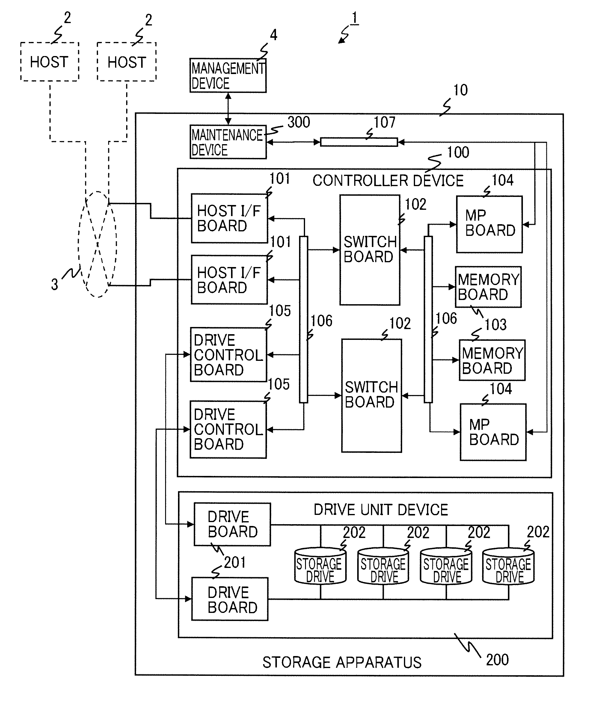
A storage apparatus includes a drive unit device including a plurality of storage drives, a drive interface unit and a power supply unit, the storage drives being configured to provide a physical storage area for creating a logical storage area to be used by an external apparatus, the drive interface unit being configured to input and output data to and from the storage drives, the power supply unit being configured to supply operation power to the storage drives and the drive interface unit, a storage controller including a plurality of processing units and a drive control interface unit, the processing units being configured to perform a data input / output process via the drive interface unit, the data input / output process including a process of writing data from the external apparatus into the storage drives and a process of reading data out of the storage drives, the drive control interface unit being configured to issue a command to the drive interface unit in response to a request from each of the processing units, a failure existence / non-existence recording part configured to record, for every attempt of each of the plurality of the processing units to perform the data input / output process via a plurality of data paths which are communication paths for performing data transfer to and from the drive interface unit of the drive unit device, whether the relevant data input / output process was successful for each of the data paths, and a failure detection unit configured to perform a power failure detection process which, in a case where one of the plurality of processing units has determined that the data input / output process with the drive interface unit has not been performed successfully, determines whether a result of the data input / output process performed by each of the other processing units has been recorded in the failure existence / non-existence recording part within a predetermined period of time after an abnormality of the relevant data input / output process has been recorded in the failure existence / non-existence recording part, and, in a case where the first processing unit which has detected the abnormality in the data input / output process has determined that the data input / output process abnormality is recorded in the failure existence / non-existence recording part for all the data paths, provides an instruction to stop the data input / output processes to the drive unit device in which the data input / output process abnormality has been detected and other drive unit devices coupled downstream of the relevant drive unit device.

Description

TECHNICAL FIELD[0001]This invention relates to a storage apparatus and a method of detecting a power failure in a storage apparatus, and particularly relates to a storage apparatus and a method of detecting a power failure in a storage apparatus, which can detect a failure occurring in a power supply system of the storage apparatus accurately and rapidly and deal with the same in a more simplified hardware configuration.BACKGROUND ART[0002]A storage apparatus is an apparatus which including storage media such as hard disk drives (Hard Disk Drives, hereinafter referred to as “HDDs”) and semiconductor storage drives (Solid State Drives, hereinafter referred to as “SSDs”), and providing storage areas of data to be processed by applications and other programs running on a host computer or the like, and is also referred to as a disk subsystem.[0003]In recent years, there has been an increasing demand that storage apparatuses should achieve further power saving, space saving, higher-densi...

Claims


Application Information

Patent Timeline
Patent Type & Authority Applications(United States)
IPC IPC(8): G06F11/22
CPCG06F1/28G11B19/047G06F1/30
Inventor NAKAYAMA, YOSUKEINOUE, TETSUYAKOGA, TSUTOMUSUZUKI
Owner HITACHI LTD
Learn More