Method and device for heat recovery on a vapour refrigeration system

a refrigeration system and vapour technology, applied in the field of methods and devices for heat recovery on vapour compression systems, can solve the problems of high electricity consumption, low cooling performance, waste of heat removed in the condensing process of refrigeration systems, etc., and achieve the effect of increasing the condensing temperatur

Inactive Publication Date: 2012-06-21
ECOLACTIS
View PDF5 Cites 12 Cited by
  • Summary
  • Abstract
  • Description
  • Claims
  • Application Information

AI Technical Summary

Benefits of technology

[0019]In one embodiment, the condensing tempera

Problems solved by technology

Usually, the refrigeration system is operated totally separate from the hot water system with the result that the heat removed in the condensing process of the refrigeration system is wasted, while the water in the hot water system is heated by means of an external energy source such as electricity;
Nevertheless, even if it allows heat recovery, this method and device has several drawbacks Firstly, the condensing temperature is constantly on a high level thus resulting globally in high electricity consumption and low cooling performance Secondly, the production of hot water is independent from the req

Method used


Image

  • Method and device for heat recovery on a vapour refrigeration system
  • Method and device for heat recovery on a vapour refrigeration system
  • Method and device for heat recovery on a vapour refrigeration system

Examples


second embodiment

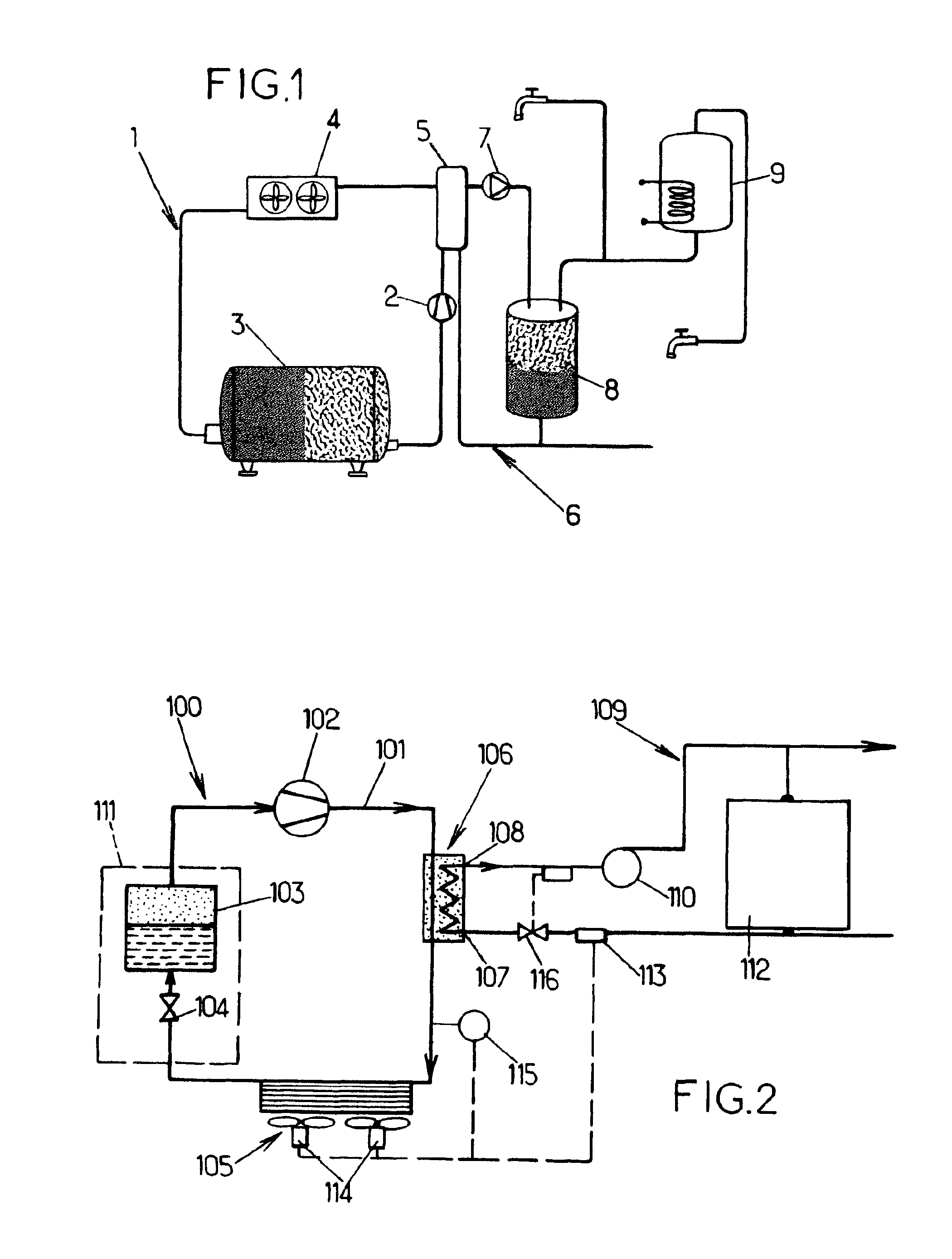
[0066]In a second embodiment, referring to FIG. 6, the device according to the invention comprises a refrigeration unit 100 including at least a first piping closed refrigerating circuit 101 in which a refrigerant fluid circulates, a compressor 102, an evaporator 103, an expansion valve 104 and a heat recovery unit 106 including a water inlet 107 and a water outlet 108 respectively connected to a second piping circuit 109 comprising a circulating pump 110 The evaporator 103 and the expansion valve 104 are embedded in a milk cooling tank 111 which is progressively filled up during cows milking.

[0067]This embodiment can be distinguished from the preceding by the fact that the air cooled condenser had been substituted by a water cooled condenser 200 including a water inlet 201 and a water outlet 202 respectively connected to a third piping circuit 203 Said third piping circuit 203 comprises a solenoid valve 204 positioned at the outlet pipe of the third piping circuit 203, the outlet o...

first embodiment

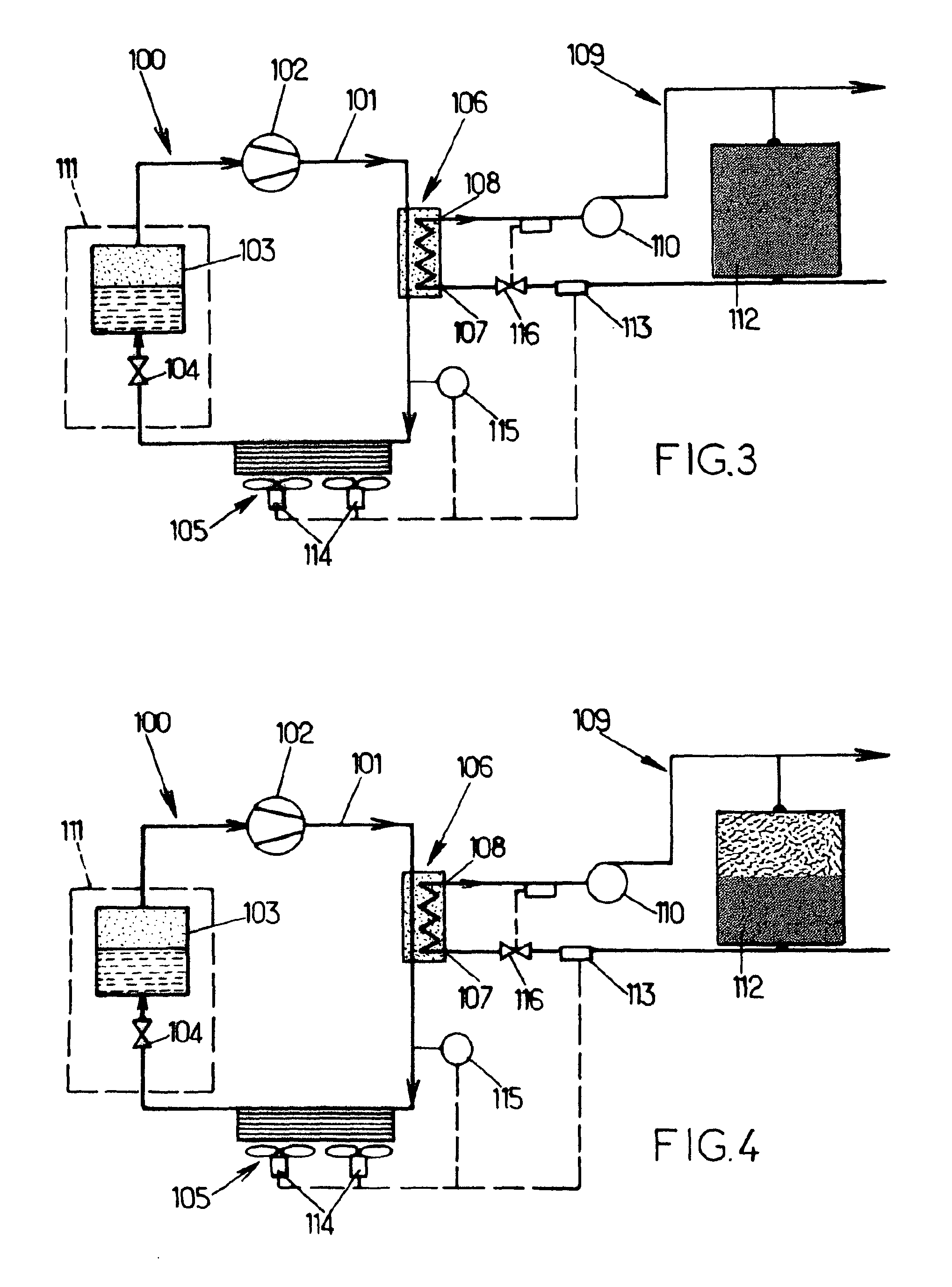
[0077]This embodiment can be distinguished from the first embodiment illustrated on FIG. 2 by the fact that the air cooled condenser had been deleted The outlet pipe of the second piping circuit 109 comprises a derivative pipe 300 including a solenoid valve 301 connected to the thermostat 113, said thermostat 113 being also connected to a solenoid valve 302 positioned between said thermostat 113 and the thermostatic valve 116 The derivative pipe 300 feeds at least one drinking trough 205 and the incoming pipe of the second piping circuit 109 comprises a by-pass circuit 304 including a pressostatic valve 305 Accesso[pi]ly, the outlet pipe of the second piping circuit 109 may comprise a non return valve 303 positioned between the circulating pump 110 and the preheated water tank 112 The incoming pipe of the second piping circuit 109 comprises a filter 306 and a by-pass circuit 307, said by-pass circuit 307 including a second filter 308 and a solenoid valve 309.

[0078]Accessorily, the d...


PUM


Abstract

A method and a device for heat recovery on a vapour compression refrigeration system allowing to produce hot water, includes at least a first piping closed refrigerating circuit in which a refrigerant fluid circulates, a compressor, an evaporator, an expansion valve, a condenser and/or a heat recovery unit including a water inlet and a water outlet respectively connected to a second piping circuit comprising a circulating pump. At least one physical unit of the refrigerant fluid and/or water of the second piping circuit is determined. When the physical unit is lower than a predetermined threshold, condensing temperature is increased, and when said physical unit is greater than said predetermined threshold, condensing temperature is decreased to a minimum value.

Description

FIELD OF THE INVENTION[0001]The invention relates in general to a method and a device for heat recovery on a vapour compression system Said method and device will be particularly useful for bulk milk coolers on farmsBACKGROUND OF THE INVENTION[0002]It is well known vapour compression refrigeration system including at least a first piping closed refrigerating circuit in which a refrigerant fluid circulates, a compressor, an evaporator, an expansion valve, a condenser, wherein the refrigerant fluid is entered in a vapour saturated state into the compressor, the refrigerant fluid is compressed to a higher pressure resulting in a higher temperature, in such a way that the refrigerant fluid is in a superheated vapour state, then the refrigerant fluid is cooled and condensed in superheated vapour state into a saturated liquid by passing it through the condenser, then the saturated liquid is passed through the expansion valve to reduce abruptly the pressure providing a flash evaporation th...

Claims


Application Information

Patent Timeline
IPC IPC(8): F25B29/00G05D23/32F25D17/00
CPCF25B29/003F25B2700/21161F25B2339/047F25B49/027A01J9/04Y02P60/87F25B6/04F25B2600/01
Inventor DECAESTECKER, LAURENT
Owner ECOLACTIS
Why Eureka
Try Eureka