
System for forming emulsions

a technology of emulsion and system, applied in the field of system for forming emulsion, can solve the problems of waste rather than testing, inability to efficiently use samples, and large portion of samples not being incorporated into the system,

Active Publication Date: 2012-06-21
BIO RAD LAB INC
View PDF3 Cites 110 Cited by
  • Summary
  • Abstract
  • Description
  • Claims
  • Application Information

AI Technical Summary

Benefits of technology

[0003]Many biomedical applications rely on high-throughput assays of samples. For example, in research and clinical applications, high-throughput genetic tests using target-specific reagents can provide accurate and precise quantification of nucleic acid targets for drug discovery, biomarker discovery, and clinical diagnostics, among others.
[0004]Emulsions hold substantial promise for revolutionizing high-throughput assays. Emulsification techniques can create large numbers of aqueous droplets that function as independent reaction chambers for biochemical reactions. For example, an aqueous sample (e.g., 20 microliters) can be partitioned into droplets (e.g., 20,000 droplets of one nanoliter each) to allow an individual test to be performed on each of the droplets.
[0005]Aqueous droplets can be suspended in oil to create a water-in-oil emulsion (W / O). The emulsion can be stabilized with a surfactant to reduce coalescence of droplets during heating, cooling, and transport, thereby enabling thermal cycling to be performed. Accordingly, emulsions have been used to perform single-copy amplification of nucleic acid target molecules in droplets using the polymerase chain reaction (PCR). Digital assays are enabled by the ability to detect the presence of individual molecules of a target in droplets.

Problems solved by technology

However, available systems may not use samples efficiently—a substantial portion of the sample may not be incorporated into the emulsion and instead may be wasted rather than tested.
Also, the systems may not be automated at all or at least not sufficiently to free the user for other tasks during emulsion formation.
In some cases, the systems may fail to be user-friendly by requiring substantial skill and training to operate successfully.
Furthermore, the systems may not provide adequate safeguards to minimize cross-contamination of samples.

Method used


Image

  • System for forming emulsions
  • System for forming emulsions
  • System for forming emulsions

Examples


Embodiment Construction

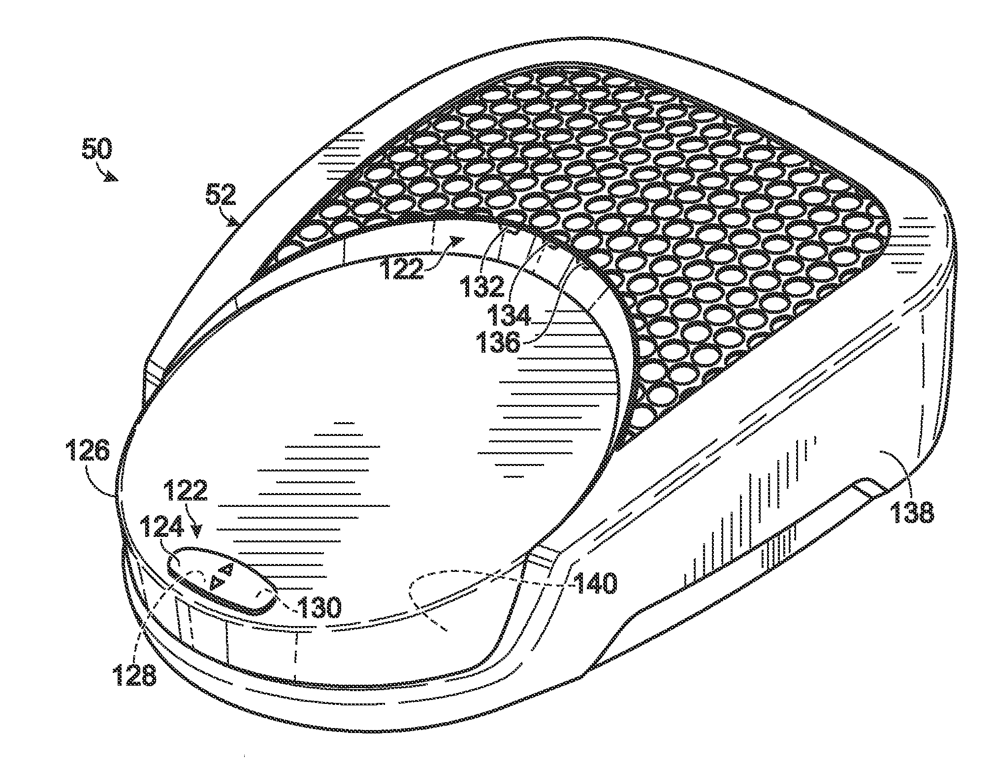
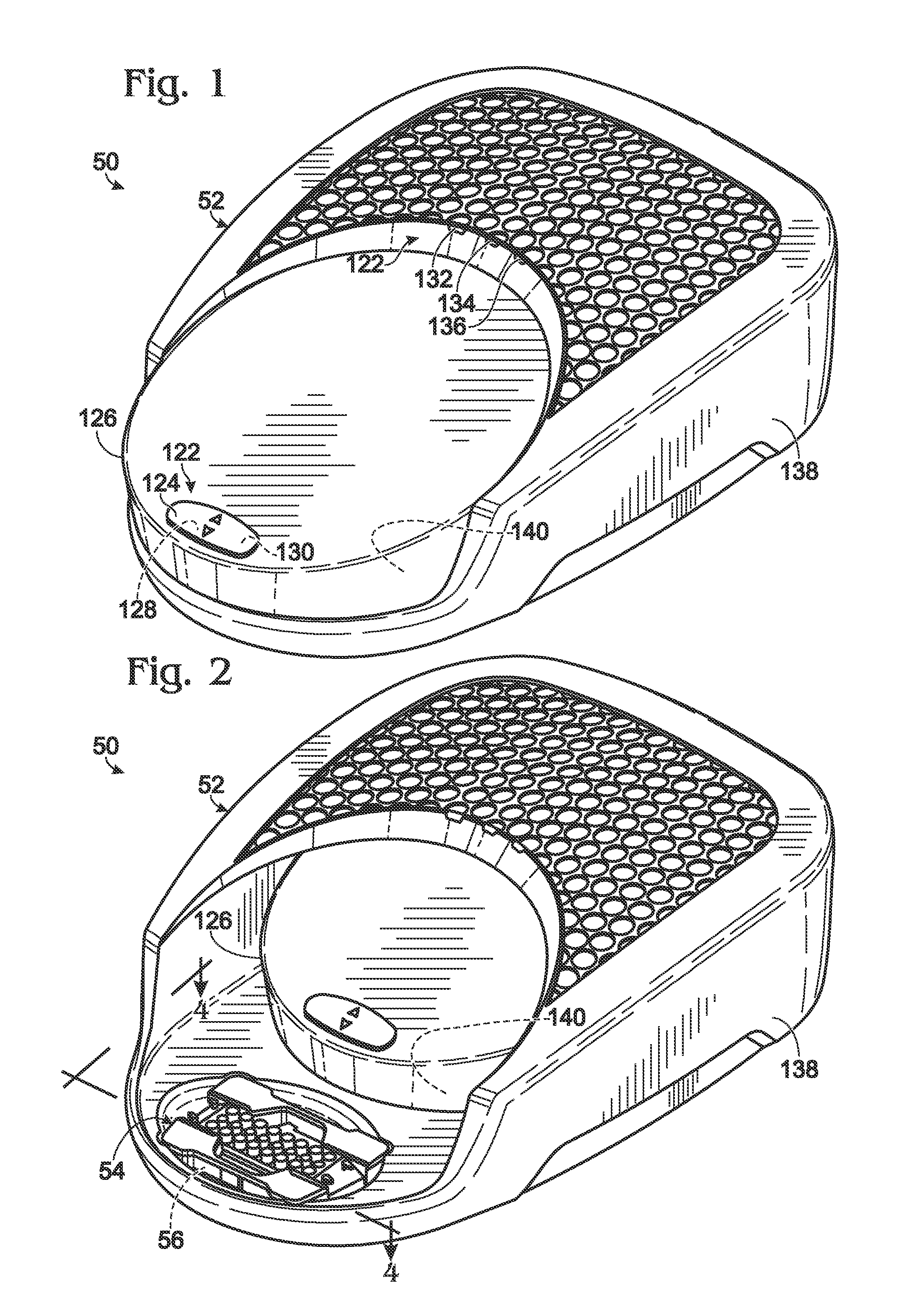
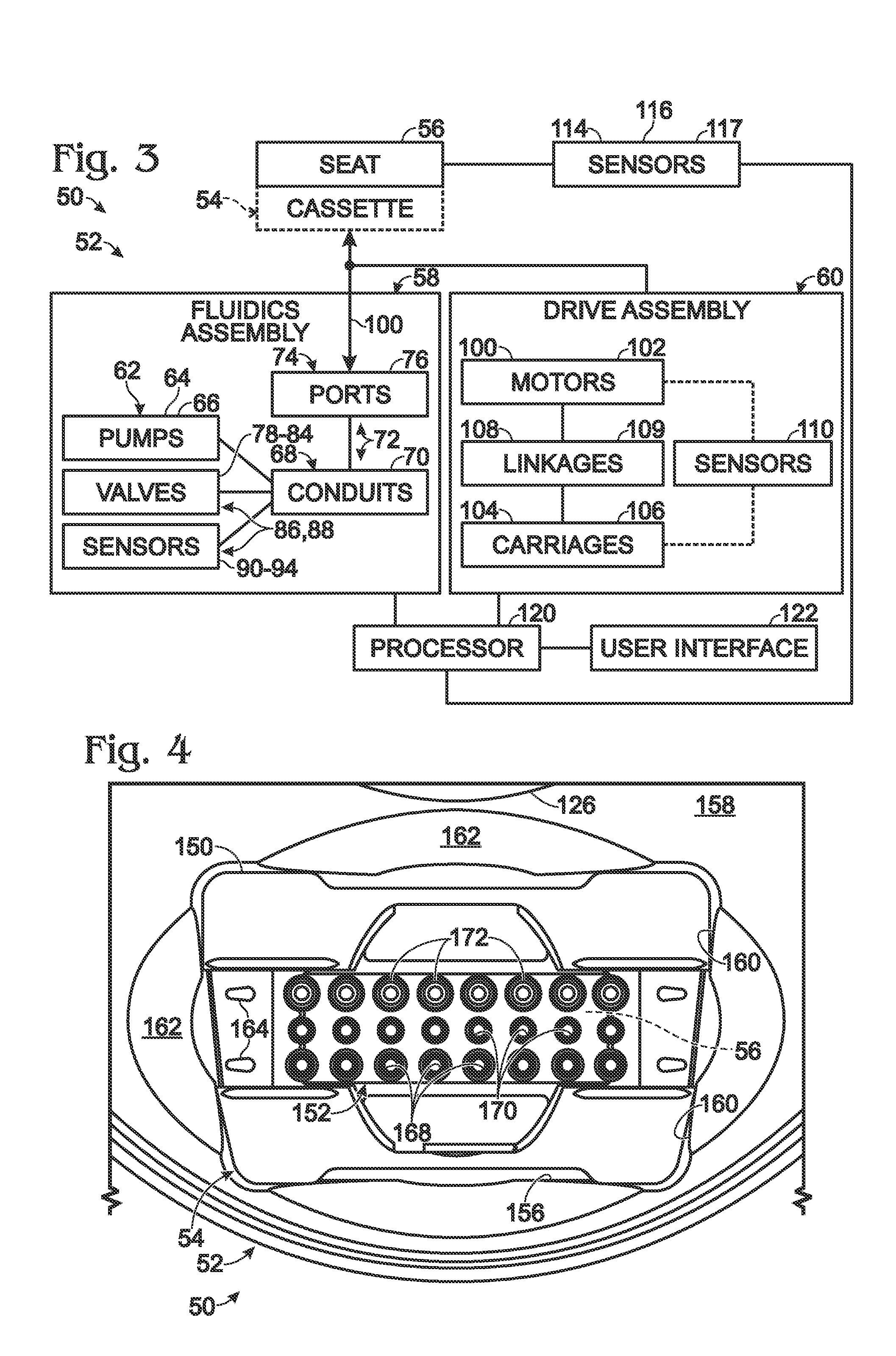
[0033]The present disclosure provides a system, including methods, apparatus, and kits, for forming emulsions. The system may include an instrument and a microfluidic chip received by the instrument. The instrument may apply pressure to prospective emulsion phases held by the chip, to drive formation and collection of emulsions in the chip. In some embodiments, the instrument may stop applying pressure to the chip when a change in pressure meeting a predefined condition is detected by the instrument. The change may indicate that an endpoint of droplet generation has been reached.

[0034]An exemplary method of emulsion formation is provided. In the method, pressure may be applied to a microfluidic chip holding prospective emulsion phases, to drive droplet formation and collection of emulsions in the chip. The pressure may be monitored for a change that meets a predefined condition. Application of the pressure may be stopped when the change is detected.

[0035]Another exemplary method of ...


PUM

PropertyMeasurementUnit
inner diameteraaaaaaaaaa

Abstract

System, including methods, apparatus, and kits, for forming emulsions. The system may include an instrument and a microfluidic chip received by the instrument. The instrument may apply pressure to prospective emulsion phases held by the chip, to drive formation and collection of emulsions in the chip. In some embodiments, the instrument may stop applying pressure to the chip when a change in pressure meeting a predefined condition is detected by the instrument. The change may indicate that an endpoint of droplet generation has been reached.

Description

CROSS-REFERENCES TO PRIORITY APPLICATIONS[0001]This application is based upon and claims the benefit under 35 U.S.C. §119(e) of U.S. Provisional Patent Application Ser. No. 61 / 409,106, filed Nov. 1, 2010; U.S. Provisional Patent Application Ser. No. 61 / 409,473, filed Nov. 2, 2010; and U.S. Provisional Patent Application Ser. No. 61 / 410,769, filed Nov. 5, 2010. Each of these provisional patent applications is incorporated herein by reference in its entirety for all purposes.CROSS-REFERENCES TO ADDITIONAL MATERIALS[0002]This application incorporates herein by reference in their entirety for all purposes the following materials: U.S. Pat. No. 7,041,481, issued May 9, 2006; U.S. Patent Application Publication No. 2010 / 0173394 A1, published Jul. 8, 2010; U.S. Patent Application Publication No. 2011 / 0217712 A1, published Sep. 8, 2011; PCT Patent Application No. WO 2011 / 120024, published Sep. 29, 2011; and Joseph R. Lakowicz, PRINCIPLES OF FLUORESCENCE SPECTROSCOPY (2nd Ed. 1999).INTRODUCT...

Claims


Application Information

Patent Timeline
Patent Type & Authority Applications(United States)
IPC IPC(8): F17D1/16F03B11/02
CPCB01F3/0807B01F13/0062B01F13/1022B01L3/502784B01L2200/0605B01L3/502761B01L2300/0867B01L2400/0487G01N1/38G01N2035/1046B01L2200/0673B01F23/4145B01F23/4105B01F25/14B01F35/2113B01F35/2213B01F2101/2202B01F2101/23B01F2101/44Y10T137/8593Y10T137/0396B01F23/41B01F33/3011B01F33/813
Inventor HIDDESSEN, AMY L.MASQUELIER, DONALD A.NESS, KEVIN D.HINDSON, BENJAMIN J.MAKAREWICZ, JR., ANTHONY J.STEENBLOCK, ERIN R.
Owner BIO RAD LAB INC
Learn More