
System for generating droplets with pressure monitoring

a technology of droplet generation and monitoring system, which is applied in the direction of laboratory glassware, instruments, reagent containers, etc., can solve the problems of waste rather than testing, large portion of sample not being incorporated into the system, and inefficient use of samples by available systems

Active Publication Date: 2017-06-01
BIO RAD LAB INC
View PDF2 Cites 7 Cited by
  • Summary
  • Abstract
  • Description
  • Claims
  • Application Information

AI Technical Summary

Benefits of technology

The patent text discusses the use of emulsions for high-throughput assays in biomedical applications such as genetic testing and clinical diagnostics. Emulsification techniques create large numbers of small droplets that can act as separate reaction chambers for biochemical reactions. These droplets can be stabilized with a surfactant to prevent coalescence, and the resulting emulsions have been used to amplify nucleic acid targets using polymerase chain reaction (PCR) and to detect the presence of individual molecules of a target. The technical effect of this patent text is to provide a method for performing high-throughput assays with improved accuracy and precision using emulsions for biochemical reactions.

Problems solved by technology

However, available systems may not use samples efficiently—a substantial portion of the sample may not be incorporated into the emulsion and instead may be wasted rather than tested.
Also, the systems may not be automated at all or at least not sufficiently to free the user for other tasks during emulsion formation.
In some cases, the systems may fail to be user-friendly by requiring substantial skill and training to operate successfully.
Furthermore, the systems may not provide adequate safeguards to minimize cross-contamination of samples.

Method used


Image

  • System for generating droplets with pressure monitoring
  • System for generating droplets with pressure monitoring
  • System for generating droplets with pressure monitoring

Examples


Embodiment Construction

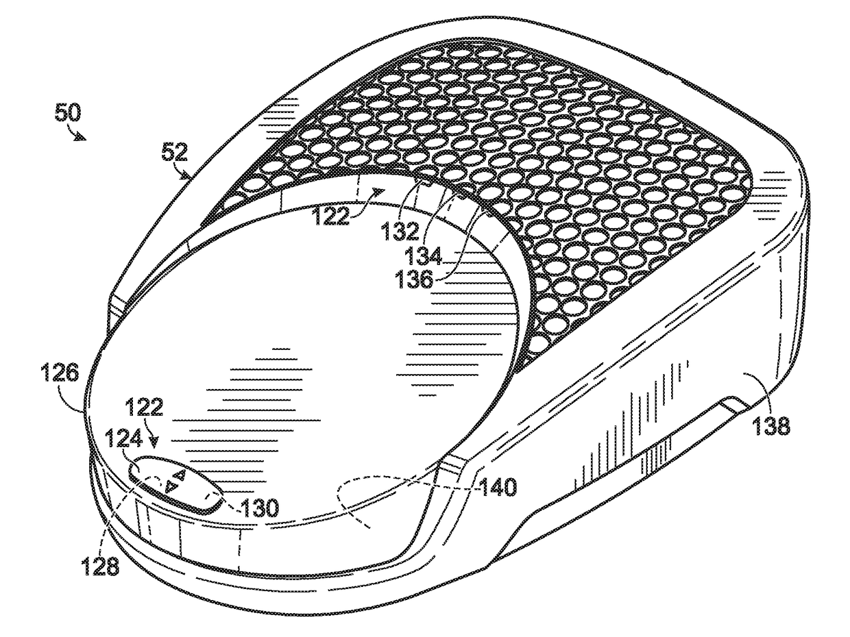
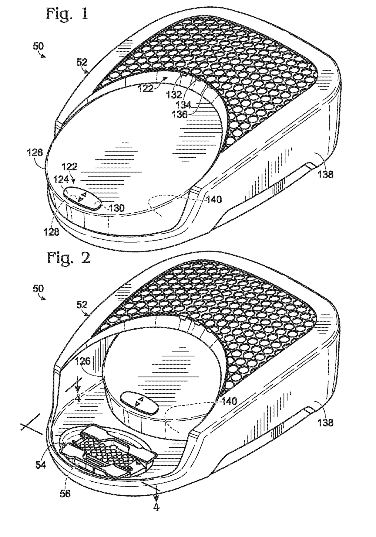
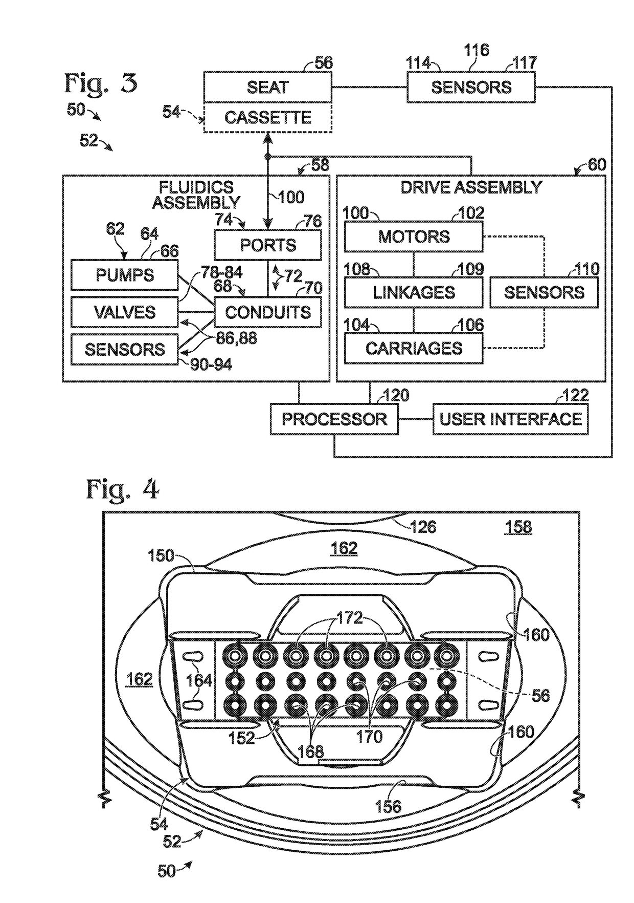
[0066]The present disclosure provides a system, including methods, apparatus, and kits, for forming emulsions. The system may include an instrument and a microfluidic chip received by the instrument. The instrument may apply pressure to prospective emulsion phases held by the chip, to drive formation and collection of emulsions in the chip. In some embodiments, the instrument may stop applying pressure to the chip when a change in pressure meeting a predefined condition is detected by the instrument. The change may indicate that an endpoint of droplet generation has been reached.

[0067]An exemplary method of emulsion formation is provided. In the method, pressure may be applied to a microfluidic chip holding prospective emulsion phases, to drive droplet formation and collection of emulsions in the chip. The pressure may be monitored for a change that meets a predefined condition. Application of the pressure may be stopped when the change is detected.

[0068]Another exemplary method of ...


PUM

PropertyMeasurementUnit
inner diameteraaaaaaaaaa

Abstract

System, including methods, apparatus, and kits, for forming emulsions. In an exemplary method of generating droplets, a device may be selected that includes a plurality of emulsion-formation units each including a sample well, a continuous-phase well, a droplet well, and a channel network that fluidically interconnects the wells and creates a droplet-generation region. A discrete volume of sample-containing fluid may be placed into the sample well of each emulsion-formation unit, and a discrete volume of continuous-phase fluid into the continuous-phase well of each emulsion-formation unit. Pressure may be applied to the device with a fluidics assembly after the step of placing, such that the plurality of emulsion-formation units generate droplets in parallel with one another. A pressure signal may be detected from the fluidics assembly. Application of the pressure may be stopped when the pressure signal indicates that a sample well is empty.

Description

CROSS-REFERENCES TO PRIORITY APPLICATIONS[0001]This application is a continuation-in-part of the following U.S. patent applications: Ser. No. 12 / 954,634, filed Nov. 25, 2010; Ser. No. 13 / 400,030, filed Feb. 17, 2012; Ser. No. 14 / 020,742, filed Sep. 6, 2013; Ser. No. 14 / 159,410, filed Jan. 20, 2014, now U.S. Pat. No. 9,492,797; Ser. No. 14 / 201,752 filed Mar. 7, 2014; and Ser. No. 14 / 848,311, filed Sep. 8, 2015.[0002]U.S. patent application Ser. No. 14 / 159,410, in turn, is a continuation-in-part of the following patent applications: Ser. No. 12 / 586,626, filed Sep. 23, 2009, now U.S. Pat. No. 9,156,010; Ser. No. 12 / 862,542, filed Aug. 24, 2010, now U.S. Pat. No. 9,194,861; Ser. No. 12 / 890,550, filed Sep. 24, 2010, now U.S. Pat. No. 8,633,015; Ser. No. 13 / 245,575, filed Sep. 26, 2011, now abandoned; Ser. No. 13 / 945,661, filed Jul. 18, 2013, now U.S. Pat. No. 9,417,190; Ser. No. 12 / 962,507, filed Dec. 7, 2010, now U.S. Pat. No. 9,216,392; Ser. No. 12 / 962,511, filed Dec. 7, 2010; Ser. No....

Claims


Application Information

Patent Timeline
Patent Type & Authority Applications(United States)
IPC IPC(8): B01L3/00C12Q1/68B01L9/00B01F23/00
CPCB01L3/50273B01F13/0071C12Q1/686B01L2200/14B01L2300/0829B01L2400/049B01L2200/16B01L2200/025B01L2300/0681B01L2300/0609B01L2200/0636B01L2300/0861B01L3/502B01F5/0085B01L3/502784B01F13/0062B01L3/502761B01L2200/0673B01L2300/0816B01F3/0807B01L3/52B01L2200/0647G01N35/08B01F5/0256B01L9/527B01L2200/027B01F23/41B01F33/3011B01F33/813B01F25/14B01F25/23B01F33/3021
Inventor HIDDESSEN, AMY L.MASQUELIER, DONALD A.NESS, KEVIN D.HINDSON, BENJAMIN J.MAKAREWICZ, JR., ANTHONY J.CHIA, ERIN R.COLSTON, JR., BILLY W.SAXONOV, SERGETZONEV, SVILEN S.LUCERO, MICHAEL Y.KOEHLER, RYAN T.
Owner BIO RAD LAB INC
Learn More