Resonant commutation system for exciting a three-phase alternator

a three-phase alternator and resonance commutation technology, which is applied in the direction of electric generator control, dynamo-electric converter control, control systems, etc., can solve the problem that the regulation of the output voltage of the alternator cannot be accomplished by controlling the excitation magnetic field

Inactive Publication Date: 2012-06-21
KOHLER CO
View PDF8 Cites 37 Cited by
  • Summary
  • Abstract
  • Description
  • Claims
  • Application Information

AI Technical Summary

Problems solved by technology

Because the excitation magnetic field is provided by a permanent magnet assembly, regulation of the alternator output voltage cannot be accomplished by controlling the excitation magnetic field.

Method used


Image

  • Resonant commutation system for exciting a three-phase alternator
  • Resonant commutation system for exciting a three-phase alternator
  • Resonant commutation system for exciting a three-phase alternator

Examples


Embodiment Construction

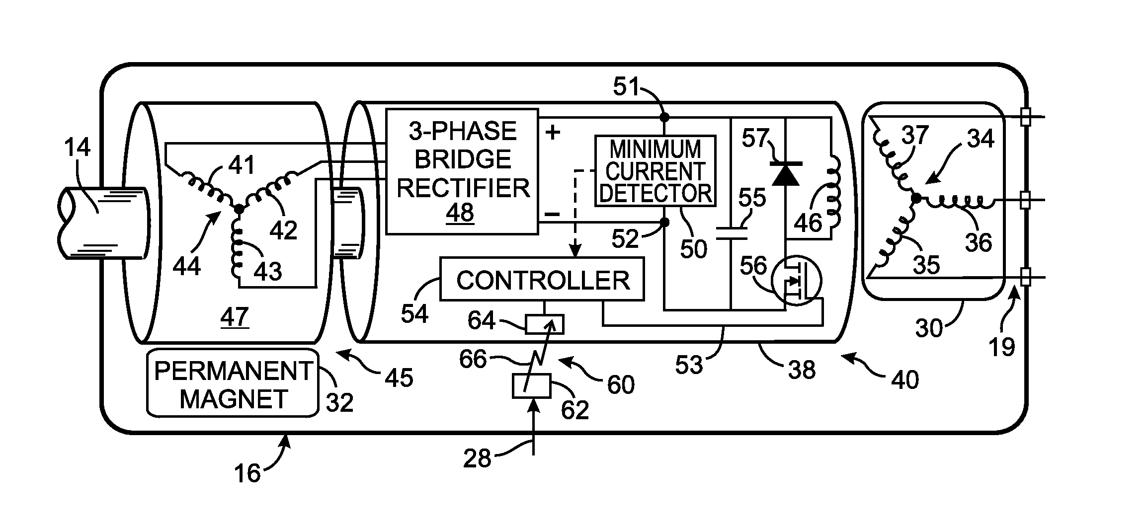
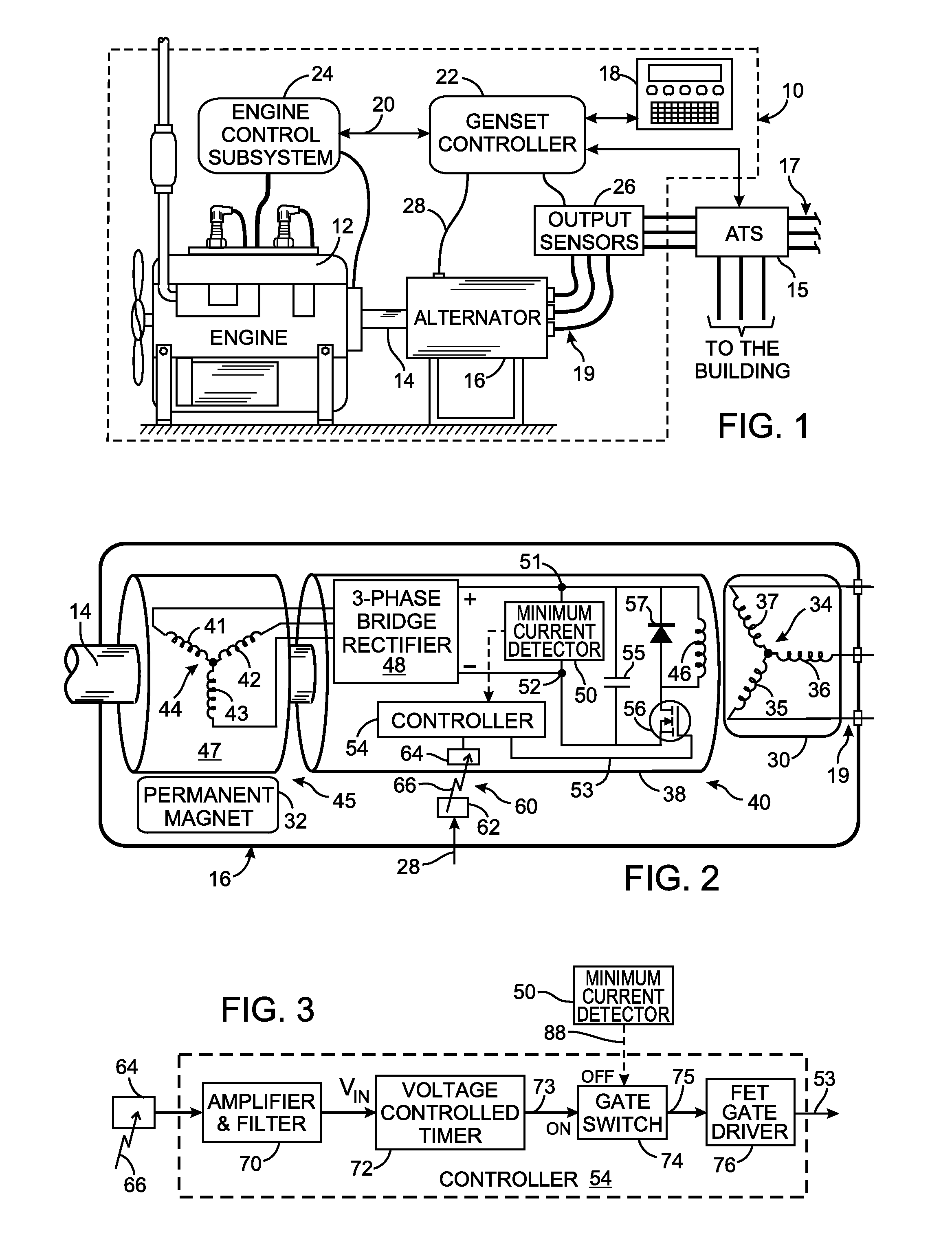
[0020]With initial reference to FIG. 1, an engine-generator set (genset) 10 comprises an prime mover, such as an internal combustion engine 12, coupled by a shaft 14 to an electrical alternator 16. This engine-generator set 10 is commonly used to provide back-up electrical power to a building in the event that power from an electric utility company is interrupted. Such interruption is automatically sensed by an automatic transfer switch (ATS) 15 that is connected to the utility lines 17 and to the outputs 19 of the alternator 16. When the automatic transfer switch 15 detects that the utility power is unavailable, a signal indicating that event is sent to the engine-generator set 10. In response to that signal, the engine 12 is started to drive the electrical alternator 16. After the alternator begins producing the nominal voltage level (e.g. 220 volts), the automatic transfer switch 15 disconnects the building's electrical wiring from the utility lines 17 and connects that wiring to...


PUM


Abstract

An alternator has a field coil that produces a magnetic field which induces electricity in an coil arrangement. A field coil excitation system includes a generator with an output coil assembly for producing alternating electricity. A rectifier converts the alternating electricity into voltage and direct current at two nodes. A capacitor, between the nodes, has capacitance that forms a resonant circuit with inductance of the output coil assembly. Due to that resonant circuit, the voltage and direct current oscillate in a predefined phase relationship. A switch and the field coil are connected in series between the nodes. A controller renders the switch conductive for a time period specified by a received control signal. The switch is rendered non-conductive at the first occurrence of a minimum current level after the time period ends. The predefined phase relationship enables the minimum current level to be detected by sensing the voltage.

Description

CROSS-REFERENCE TO RELATED APPLICATIONS[0001]Not ApplicableSTATEMENT REGARDING FEDERALLY SPONSORED RESEARCH OR DEVELOPMENT[0002]Not ApplicableBACKGROUND OF THE INVENTION[0003]1. Field of the Invention[0004]The present invention relates to circuits and methods for exciting a field coil of an electrical generator.[0005]2. Description of the Related Art[0006]Homes and commercial buildings commonly have an electrical backup generator system in which an internal combustion engine drives an electrical alternator that provides electricity when power is unavailable from an electric utility company. A controller responds to the interruption of the utility company power by automatically starting the engine. When the alternator reaches operating speed, the controller activates an automatic transfer switch to disconnect selected electrical circuits within the building from the utility power lines and connect those circuits to the output of the alternator. When the controller senses restoration ...

Claims


Application Information

Patent Timeline
Patent Type & Authority Applications(United States)
IPC IPC(8): H02P9/02
CPCH02P9/04H02P9/02H02P9/302H02P9/08H02P9/38
Inventor ALBSMEIER, ERIC D.
Owner KOHLER CO
Why Eureka
Try Eureka