

Methods and apparatuses for combinations of current feedback for frequency compensation, overload detection, and super overload detection in switching power conversion
- Summary
- Abstract
- Description
- Claims
- Application Information
AI Technical Summary
Benefits of technology
Problems solved by technology
Method used
Image

Examples
Embodiment Construction
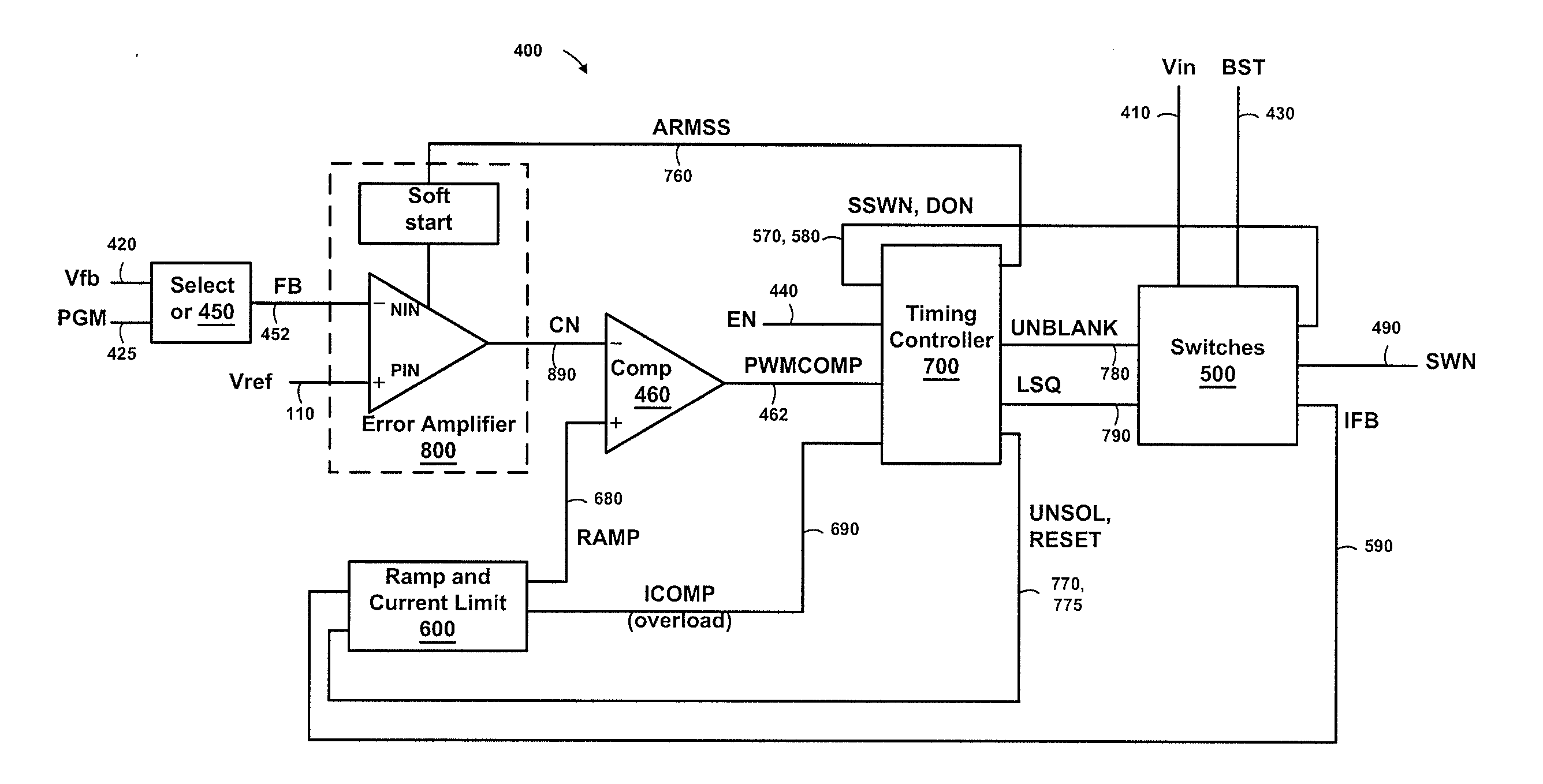
[0024]In the following description, elements, circuits, and functions may be shown in block diagram form in order not to obscure the present invention in unnecessary detail. Conversely, specific implementations shown and described are exemplary only and should not be construed as the only way to implement the present invention unless specified otherwise herein. Additionally, block definitions and partitioning of logic between various blocks is exemplary of a specific implementation. It will be readily apparent to one of ordinary skill in the art that the present invention may be practiced by numerous other partitioning solutions. For the most part, details concerning timing considerations and the like have been omitted where such details are not necessary to obtain a complete understanding of the present invention and are within the abilities of persons of ordinary skill in the relevant art.
[0025]Furthermore, in this description of embodiments of the invention, reference is made to ...
PUM
 Abstract
Description
Claims
Application Information