Optical Article and Method for Producing Optical Article

a technology of optical articles and optical coatings, applied in the field of optical articles, can solve the problems of high complexity of antireflection coating performance and functions, difficult to ensure yield in antireflection coating formation, and high complexity of production methods. achieve the effect of high performan

Inactive Publication Date: 2012-06-21
HOYA LENS MFG PHILIPPINES
View PDF8 Cites 33 Cited by
  • Summary
  • Abstract
  • Description
  • Claims
  • Application Information

AI Technical Summary

Benefits of technology

[0023]In this way, an antireflection coating can be deposited that has high levels of performance (various characteristics) required for the antireflection coating, including antireflectivity, scratch resistance, heat resistance, ...

Problems solved by technology

However, regardless of the configuration, the producing method is complex, because the deposition of the antireflection coating requires varying the vapor deposition components within a single layer, or providing three, four, or even more main components of different properties to form the high-refractive-index layer.
This is d...

Method used


Image

  • Optical Article and Method for Producing Optical Article
  • Optical Article and Method for Producing Optical Article
  • Optical Article and Method for Producing Optical Article

Examples


first embodiment

1. First Embodiment

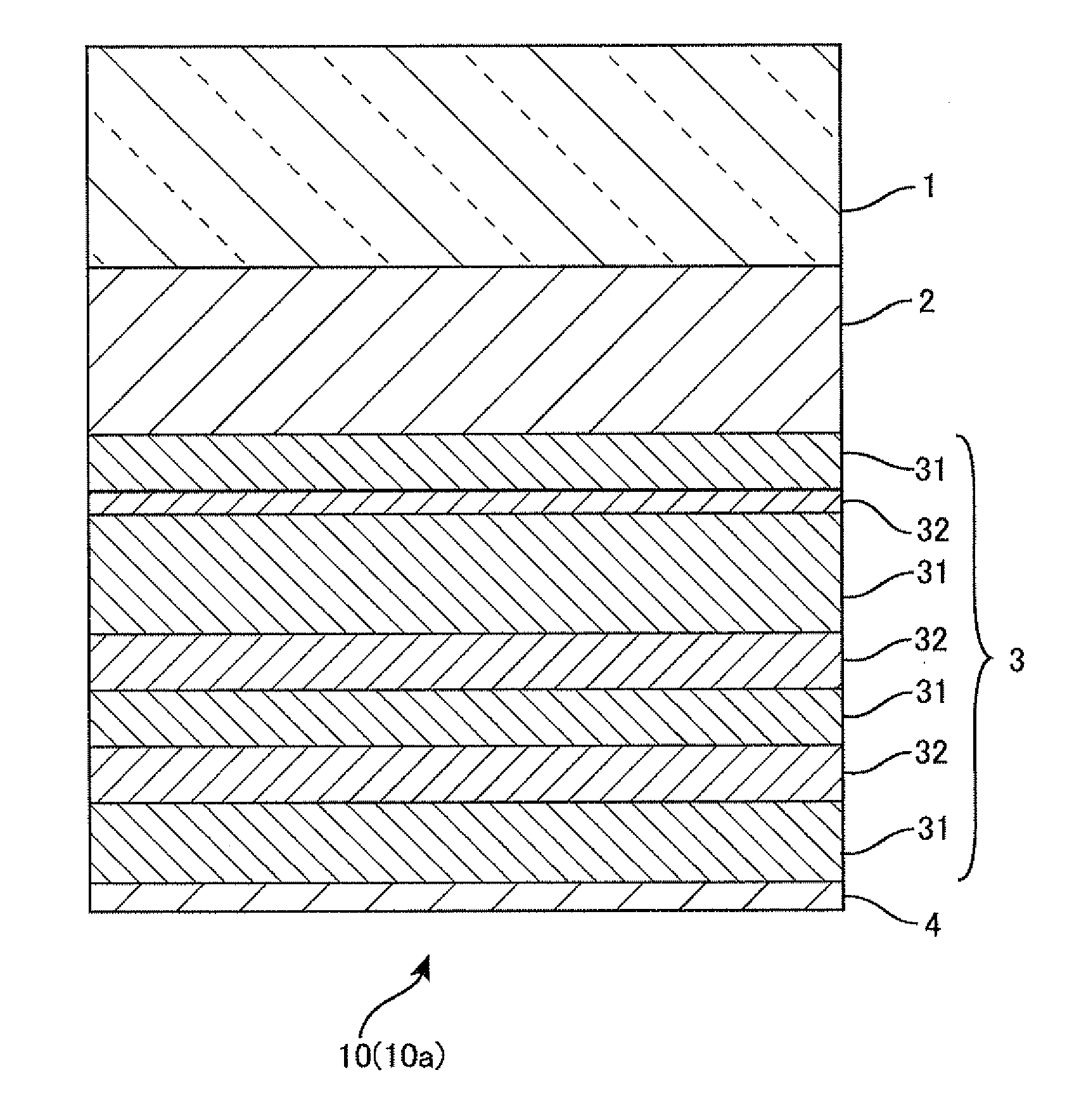
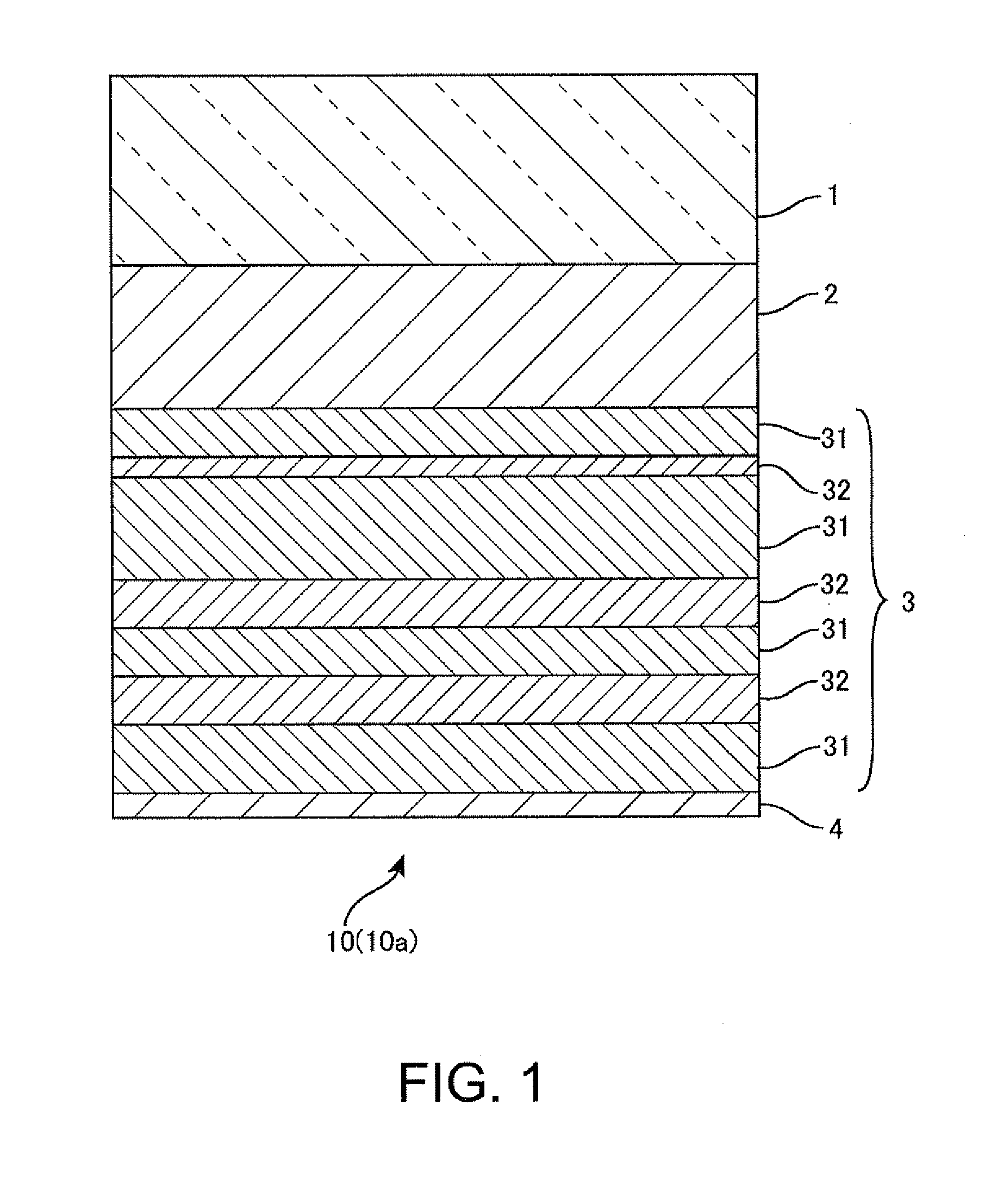
[0051]FIG. 1 shows a cross sectional configuration of a lens of First Embodiment of the invention on one side of the lens relative to the base material at the center. FIG. 1 represents the laminated layers on the lower side of the base material I at the center. Accordingly, in the following, the layers laminated on the outer sides (upper side and lower side) will be described as upper layers. A lens (optical article) 10 (10a) includes a lens base material (optical base material) 1, a hardcoat layer 2 formed on a surface of the lens base material 1, a translucent, multilayer antireflection coating 3 formed on the hardcoat layer 2, and an antifouling layer 4 formed on the antireflection coating 3. In the following, the lens will be collectively (commonly) referred to as lens 10, and the lens of First Embodiment as lens 10a.

1.1 Lens Base Material

[0052]The lens base material 1 is not particularly limited, and may be (meth)acrylic resin. Other examples include allyl c...

first embodiment (

2. Examples of First Embodiment (Antireflection Coating: 7-Layer Structure)

[0071]Samples (Examples 1 to 5, Comparative Examples 1 to 3) were produced for the lens 10a that includes an antireflection coating 3 of a total of seven layers. FIG. 3 schematically illustrates an example of a vapor deposition apparatus used to produce the samples of Examples and Comparative Examples. FIG. 4 and FIG. 5 summarize the layer structures of the samples of Examples and Comparative Examples produced for the 7-layer antireflection coating 3. FIG. 6 summarizes the deposition conditions of the low-refractive-index layer (SiO2 layer, third-type layer) 63, the first-type high-refractive-index layer (first-type layer, ZrO2 layer) 61, and the second-type high-refractive-index layer (second-type layer, TiO2 layer) 62 included in the antireflection coating 3.

2.1 Example 1 (Sample S1)

2.1.1 Selection of Lens Base Material and Deposition of Hardcoat Layer

[0072]An eyeglass plastic lens base material (refractive...

second embodiment

3. Second Embodiment

[0145]FIG. 8 shows a cross sectional configuration of a lens of Second Embodiment of the invention on one side of the lens relative to the base material at the center. A lens (optical article) 10 (10b) includes a lens base material (optical base material) 1, a hardcoat layer 2 formed on the surface of the lens base material 1, a translucent, multilayer antireflection coating 3 formed on the hardcoat layer 2, and an antifouling layer 4 formed on the antireflection coating 3. The antireflection coating 3 has five layers (n=2), in which the first, third, and fifth layers represent the low-refractive-index layers 31, and the second and fourth layers represent the high-refractive-index layers 32. The other configuration is the same as that of First Embodiment, and explanations thereof are omitted using the same reference numerals in the appended figures.

[0146]Samples (Examples 6 and 7, Comparative Examples 4 and 5) were produced for the lens 10b that includes the 5-la...


PUM

PropertyMeasurementUnit
Fractionaaaaaaaaaa
Fractionaaaaaaaaaa
Fractionaaaaaaaaaa

Abstract

An optical article includes an antireflection coating that is configured from alternately laminated n+1 low-refractive-index layers and n high-refractive-index layers (where n is an integer of 2 or more) . At least one of the n high-refractive-index layers is a first-type layer formed by vapor deposition using only a first deposition source that includes zirconium oxide as the main component. The remaining layers) in the n high-refractive-index layers is a second-type layer (s) formed by vapor deposition using only a second deposition source that includes titanium oxide as the main component. The n+1 low-refractive-index layers are third-type layers formed by vapor deposition using only a third deposition source that includes silicon oxide as the main component. The proportion of the total thickness of the second-type layer (s) in the total thickness of the n high-refractive-index layers is from 15% to 90%.

Description

CROSS-REFERENCE[0001]This application claims priority to Japanese Patent Application No. 2010-278919, filed Dec. 15, 2010, the entirety of which is hereby incorporated by reference.BACKGROUND[0002]1. Technical Field[0003]The present invention relates to optical articles for use in optical materials and products, including lenses such as an eyeglass lens, and to methods for producing such optical articles.[0004]2. Related Art[0005]JP-A-2009-42278 discloses providing an antireflection coating and optical members using the same with which the occurrence of scratches and cracks due to external impact can be suppressed. The antireflection coating includes low-refractive-index layers and high-refractive-index layers alternately laminated from the substrate side in such a manner that the low-refractive-index layers represent the outermost layers. At least one buffer layer of metal oxide is provided between the low-refractive-index layers and the high-refractive-index layers. The low-refrac...

Claims


Application Information

Patent Timeline
IPC IPC(8): G02B1/11B05D5/06
CPCG02B1/115
Inventor NISHIMOTO, KEIJISEKI, HIROYUKI
Owner HOYA LENS MFG PHILIPPINES
Why Eureka
Try Eureka