
Light emitting diode floodlight

Inactive Publication Date: 2012-06-21
YUYANG D&U CO LTD
View PDF11 Cites 19 Cited by
  • Summary
  • Abstract
  • Description
  • Claims
  • Application Information

AI Technical Summary

Benefits of technology

[0009]Therefore, the present disclosure has been made in an effort to provide an LED floodlight, which can be promptly turned on, can be semi-permanent, can save energy remarkably, and can transfer light accurately to a desired illumination region by enhancing a light concentrating effect and an illumination intensity of a central region.
[0011]According to the disclosure as described above, an LED floodlight can provide a focused illumination of desired areas by a three-dimensional light source arrangement and a high-intensity illumination reflector. Therefore, the disclosed LED floodlight can accurately transmit light to a desired illumination region by focusing the light and enhancing the illumination intensity of the focused region. Also, the LED floodlight can be promptly turned on, can be semi-permanently used, can save energy remarkably, and can be applied to an illumination apparatus requiring a specific condition as in industrial facilities.

Problems solved by technology

However, since the conventional floodlights utilize metal halide lamps, sodium lamps, or halogen lamps for their light sources, drawbacks of these sources are reflected in the form of high consumption of electricity, short operating life, slow lighting start, steep maintenance cost, and especially pollution of environment.
However, LED floodlights characteristically project lights perpendicularly to the mounting surfaces of the LEDs rendering the floodlights to have a limited radiation angle.
Moreover, even if it is a requirement for an industrial floodlight being capable of intensely illuminating a target area, uneven distribution of the intensity of illumination lowers the average intensity failing to concentrate light with the center of the illuminated area which falls short of achieving the purpose and the effect of the lighting installation.

Method used


Image

  • Light emitting diode floodlight
  • Light emitting diode floodlight
  • Light emitting diode floodlight

Examples


Embodiment Construction

[0018]Hereinafter, an exemplary embodiment of the present disclosure will be described with reference to the accompanying drawings. In the following description, the same elements will be designated by the same reference numerals although they are shown in different drawings. Further, in the following description of the present disclosure, a detailed description of known functions and configurations incorporated herein will be omitted when it may make the subject matter of the present disclosure rather unclear.

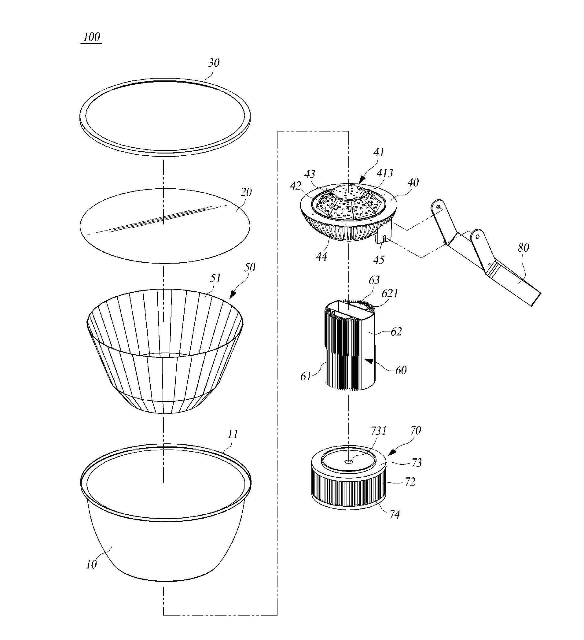
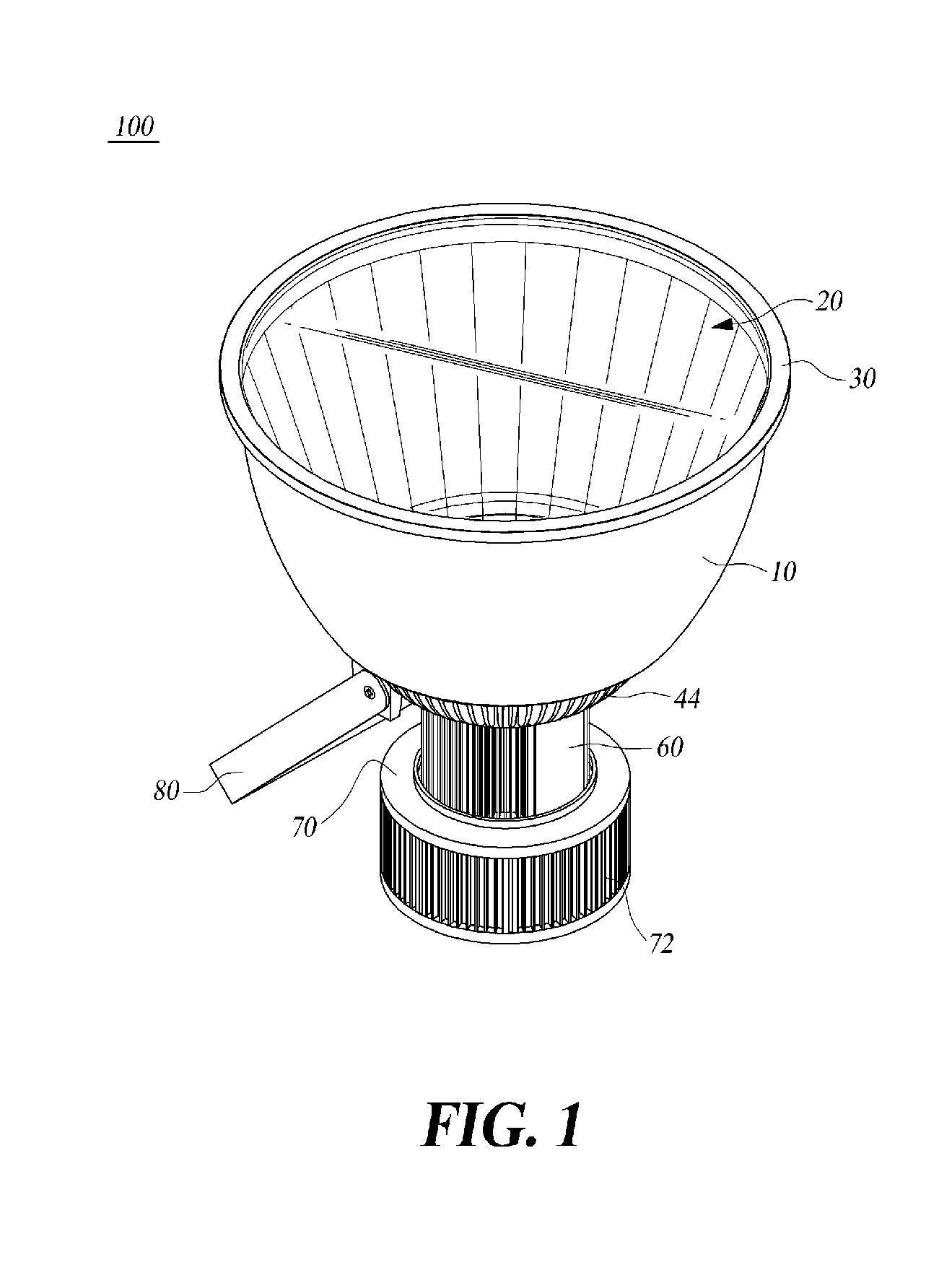
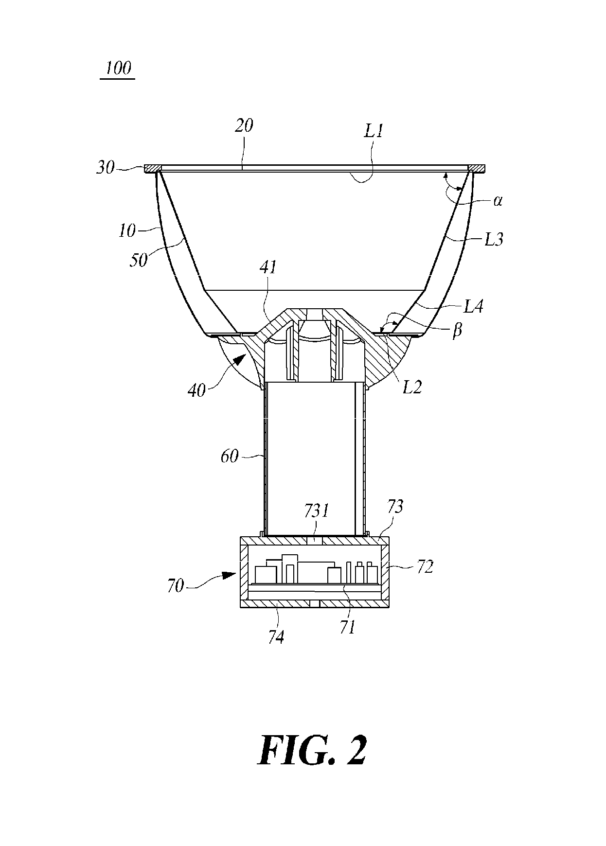
[0019]FIG. 1 is a perspective view of an LED floodlight, FIG. 2 its sectional view, FIG. 3 its plan view, and FIG. 4 is an exploded view of the LED floodlight according to an aspect of the disclosure.

[0020]As shown in the figures, the LED floodlight 100 according to the embodiment of the present disclosure includes a hollow housing 10; a lens 20 provided at one end of the housing 10; a cover 30 coupled to the end of the housing 10 and configured to hold and support the lens 20...


PUM


Abstract

A light emitting diode floodlight includes a hollow housing, a lens, a cover, a light source, an illumination reflector, an intermediate portion, and a power source. The cover is coupled to the end of the housing and configured to hold and support the lens. The light source has a pyramidal frustum-shaped portion installed at an opposite end of the housing. The illumination reflector is installed within the housing so as to surround a periphery of the pyramidal frustum-shaped portion of the light source. The intermediate portion is connected to a first heat sink of the light source and has a second heat sink on an outer peripheral surface thereof. The power source has a power supply electrically connected to the light source.

Description

CROSS-REFERENCE TO RELATED APPLICATION[0001]This application claims the priority of Korean Patent Application No. 10-2010-0129682, filed on Dec. 17, 2010 in the Korean Intellectual Property Office, the disclosure of which is incorporated herein in their entirety by reference.TECHNICAL FIELD[0002]The present disclosure relates to a light emitting diode (LED) floodlight. More particularly, the present disclosure relates to an LED floodlight for the focused illumination of desired areas by a three-dimensional light source arrangement and a high-intensity illumination reflector.BACKGROUND OF THE DISCLOSURE[0003]The statements in this section merely provide background information related to the present disclosure and may not constitute prior art.[0004]Floodlights are generally installed indoors or outdoors for irradiating desired illuminations to building structures, gigantic monuments, stadiums, plant equipments, and industrial facilities.[0005]These floodlights are made by using mainly...

Claims


Application Information

Patent Timeline
IPC IPC(8): F21V29/00F21V21/00F21V13/02
CPCF21S8/036F21V7/048F21V7/09F21V15/01F21V21/116F21V21/30F21V29/74F21V23/02F21Y2101/02F21Y2111/007F21V29/507F21V29/713F21V23/007F21Y2115/10F21Y2107/40
Inventor KIM, SANG OKKIM, BYUNG OHCHO, MIN JINLEE, IN SU
Owner YUYANG D&U CO LTD
Learn More