
Light emitting module and backlight unit using the same

a technology of light emitting modules and backlight units, applied in non-linear optics, lighting and heating apparatuses, instruments, etc., can solve the problems of low color reproducibility, low color reproducibility, and inability to meet the needs of a smaller-sized and lighter-weight lcd panel, so as to improve reliability and improve color reproducibility. , the effect of improving the efficiency

Inactive Publication Date: 2012-06-21
SAMSUNG ELECTRONICS CO LTD
View PDF11 Cites 24 Cited by
  • Summary
  • Abstract
  • Description
  • Claims
  • Application Information

AI Technical Summary

Benefits of technology

[0011]An aspect of the present invention provides a light emitting module having superior color reproducibility and light emitting efficiency while having improved reliability by creating a stable coupling, and a backlight unit using the same.
[0012]An aspect of the present invention also provides a light emitting module improved in operational efficiency in terms of simplification in the manufacturing and assembly processes thereof and allowing for a reduction in costs by standardizing a wavelength conversion part as compared with a conventional method of applying phosphors to a light emitting device, and a backlight unit using the same.
[0013]An aspect of the present invention also provides a light emitting module avoiding changes in the light emission characteristics of a light emitting device package by preventing the deterioration of a wavelength conversion part that may be caused by heat generated from a light emitting device since it is not necessary to coat an adhesive in order to apply phosphors to an upper surface of a light emitting diode package, and a backlight unit using the same.

Problems solved by technology

The CCFL employs mercury gas, which may trigger environmental pollution.
Besides, the CCFL is slow in response rate, low in color reproducibility and inappropriate for a smaller-sized and lighter-weight LCD panel.

Method used


Image

  • Light emitting module and backlight unit using the same
  • Light emitting module and backlight unit using the same
  • Light emitting module and backlight unit using the same

Examples


Embodiment Construction

[0048]Exemplary embodiments of the present invention will now be described in detail with reference to the accompanying drawings.

[0049]The invention may, however, be embodied in many different forms and should not be construed as being limited to the embodiments set forth herein. Rather, these embodiments are provided so that this disclosure will be thorough and complete, and will fully convey the scope of the invention to those skilled in the art.

[0050]In the drawings, the shapes and dimensions may be exaggerated for clarity, and the same reference numerals will be used throughout to designate the same or like components.

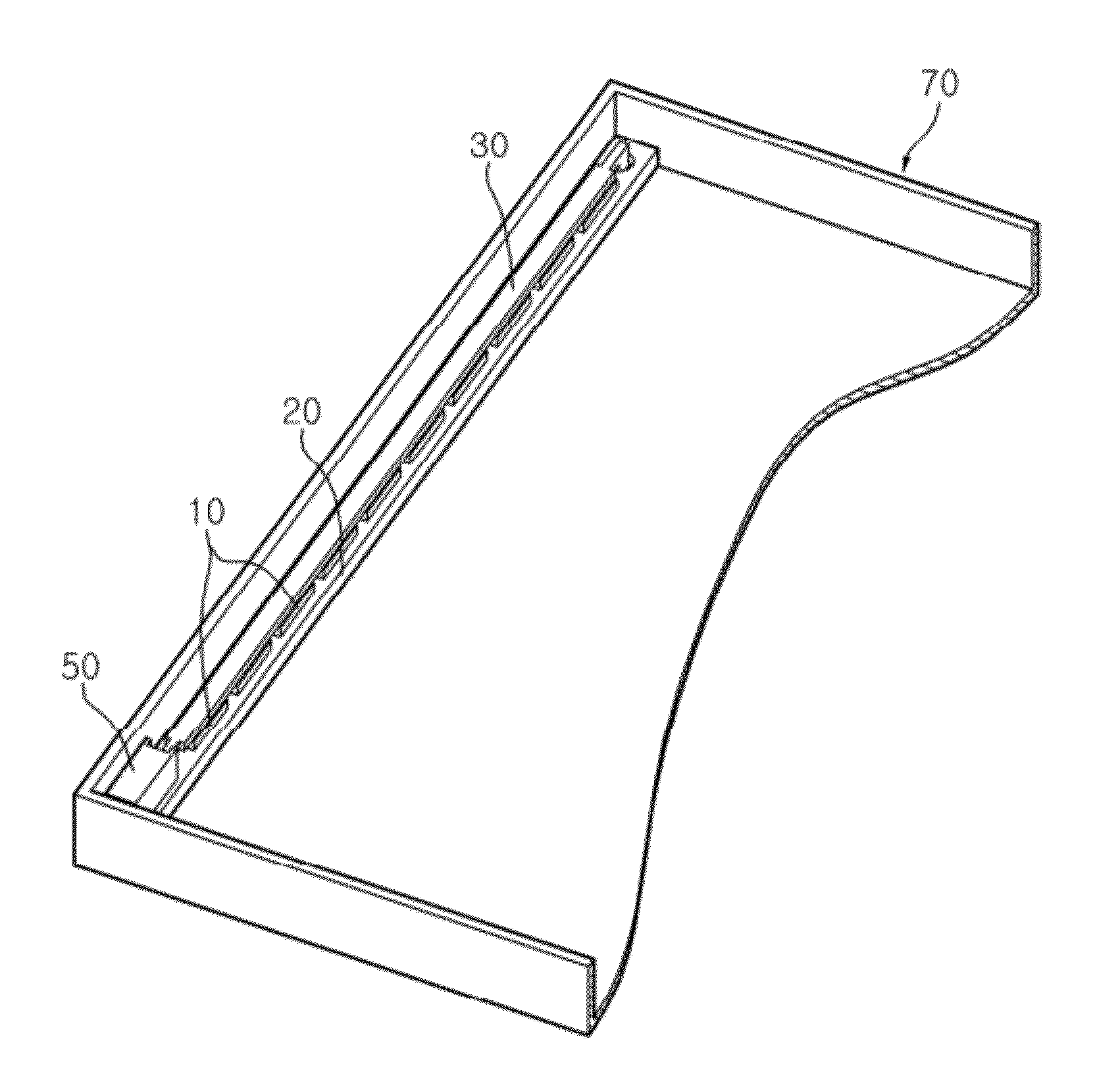
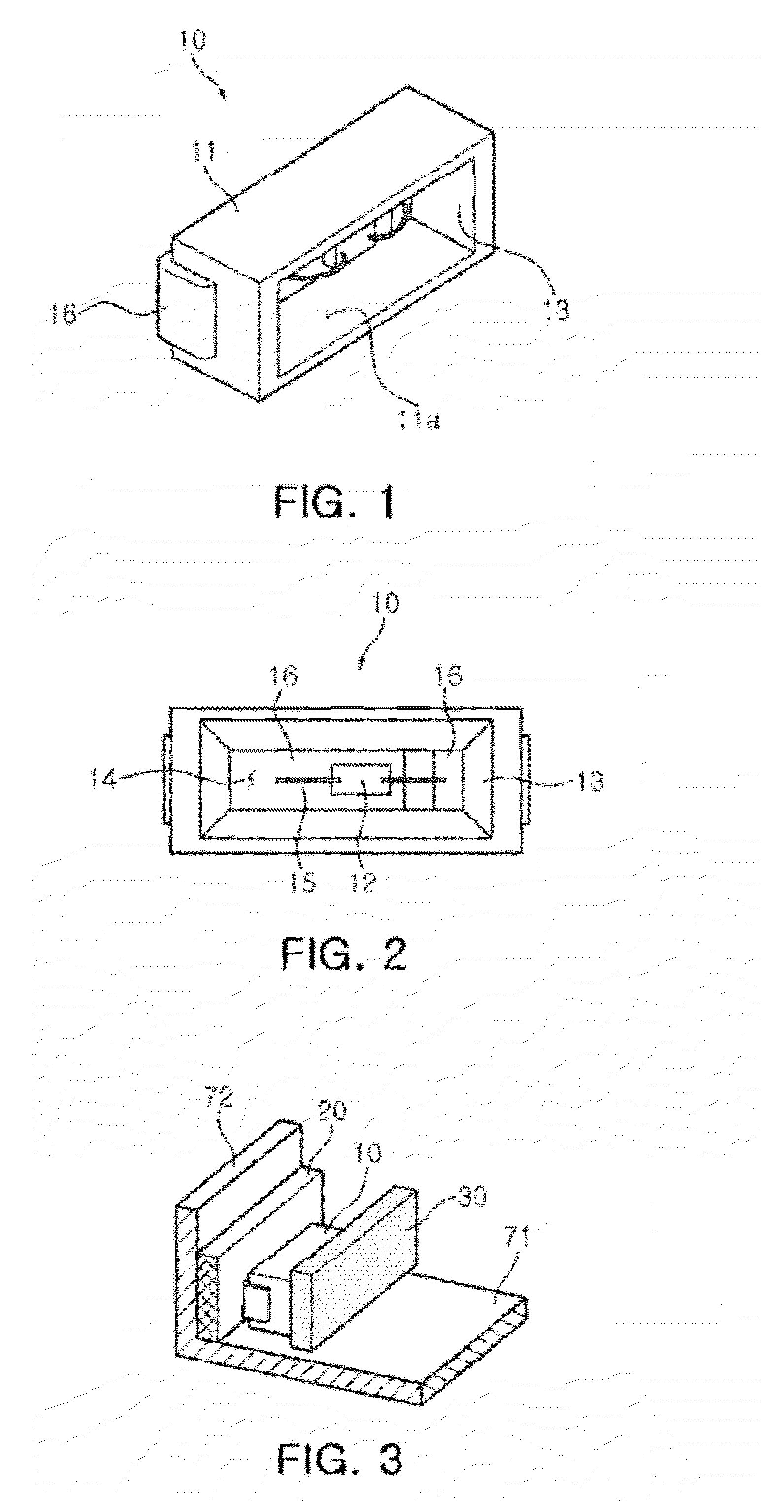
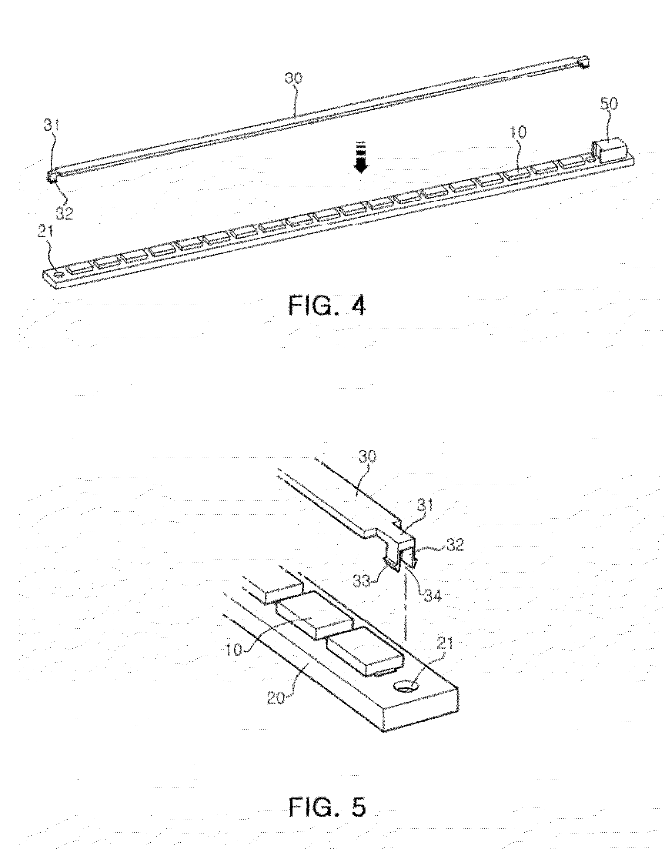
[0051]Referring to FIGS. 1 through 6, alight emitting module according to an exemplary embodiment of the invention includes a circuit board 20, at least one light source part 10 disposed on the circuit board 20, and a wavelength conversion part 30 disposed to cover a light emitting surface of the light source part 10 and allow a wavelength of light to be converted....


PUM


Abstract

There is provided a light emitting module including: a circuit board; at least one light source part disposed on the circuit board; a wavelength conversion part coupled with the circuit board, the wavelength conversion part covering alight emitting surface of the light source part and converting a wavelength of light; and a coupling part coupling the wavelength conversion part to the circuit board.

Description

CROSS-REFERENCE TO RELATED APPLICATIONS[0001]This application claims the priority of Korean Patent Application No. 10-2010-0128994 filed on Dec. 16, 2010, in the Korean Intellectual Property Office, the disclosure of which is incorporated herein by reference.BACKGROUND OF THE INVENTION[0002]1. Field of the Invention[0003]The present invention relates to a light emitting module and a backlight unit using the same.[0004]2. Description of the Related Art[0005]A light emitting diode (LED) is a semiconductor device that can emit light of various colors due to electron-hole recombination occurring at a p-n junction when a current is supplied thereto.[0006]LEDs are greatly advantageous over filament-based light emitting devices since LEDs have a long lifespan, low power usage, superior initial-operation characteristics, and high vibration resistance. These factors have continually boosted the demand for LEDs.[0007]Particularly, group III nitride semiconductors that can emit light in the bl...

Claims


Application Information

Patent Timeline
Patent Type & Authority Applications(United States)
IPC IPC(8): F21V8/00F21V9/00F21V9/16B82B1/00B82Y20/00
CPCG02F1/133603H01L25/0753H01L33/507H05K3/0067H01L2224/48091H01L2924/00H01L2924/00014
Inventor JANG, KYU HO
Owner SAMSUNG ELECTRONICS CO LTD
Learn More