Ultrasound diagnosis apparatus

a technology of ultrasound and diagnostic equipment, applied in the field of ultrasound diagnostic equipment, can solve the problems of reducing the sensitivity of image data and artifacts, and achieve the effects of reducing sensitivity, high sensitivity, and reducing signal strength in that area

Inactive Publication Date: 2012-06-21
KK TOSHIBA +1
View PDF4 Cites 14 Cited by
  • Summary
  • Abstract
  • Description
  • Claims
  • Application Information

AI Technical Summary

Benefits of technology

[0004]However, when scanning a certain area, even if image data with high sensitivity is obtained with transmission beams of a specific deflection angle, when scanning is performed with transmission beams of a different deflection angle, image data with reduced sensitivity may be obtained. When image data with high sensitivity and image data with low sensitivity are thus averaged, the signal strength of that area is decreased. Methods of preventing decreases in signal str

Problems solved by technology

However, when scanning a certain area, even if image data with high sensitivity is obtained with transmission beams of a specific deflection angle, when scanning is performed with transmission beams of a d

Method used


Image

  • Ultrasound diagnosis apparatus
  • Ultrasound diagnosis apparatus
  • Ultrasound diagnosis apparatus

Examples


first embodiment

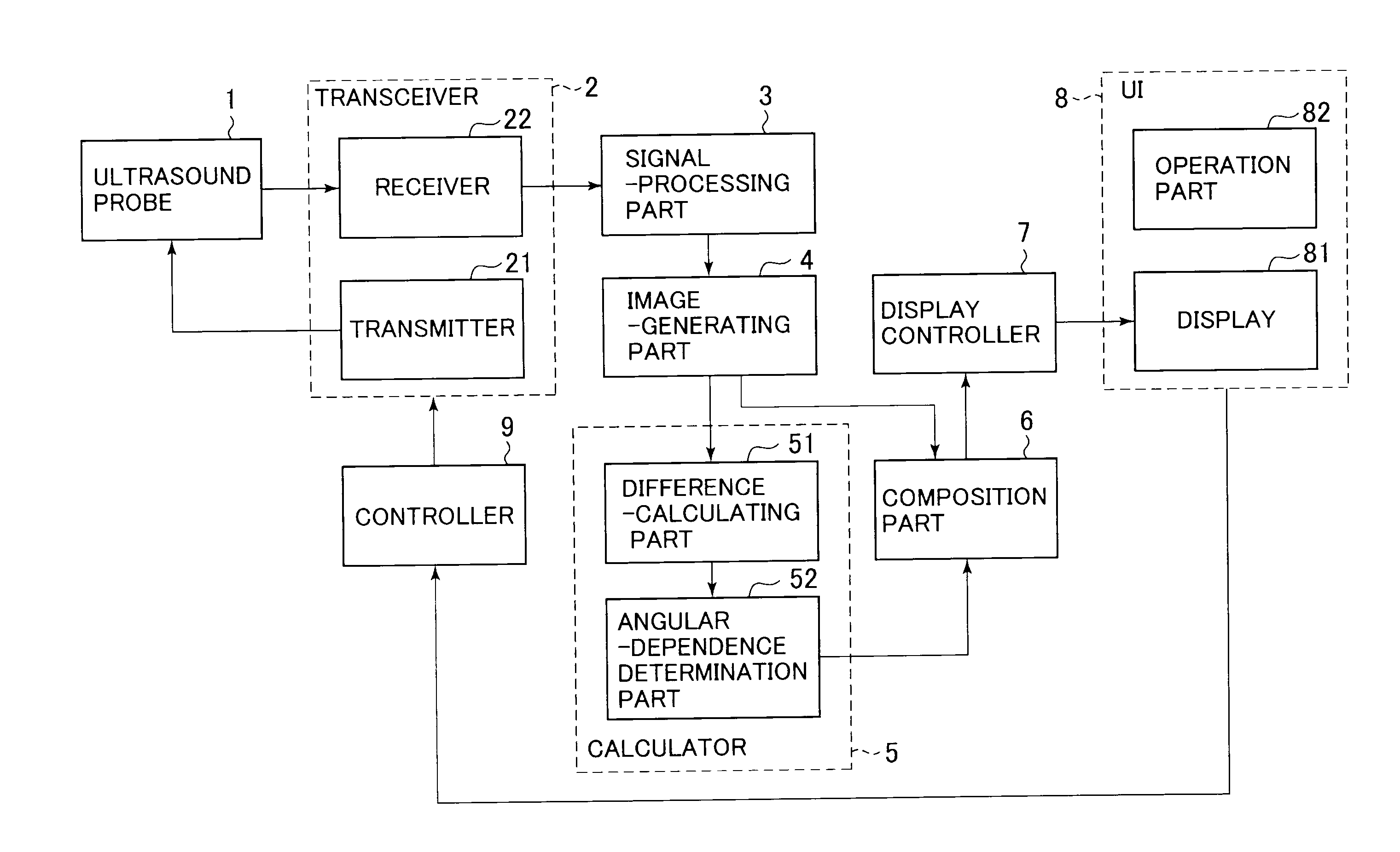
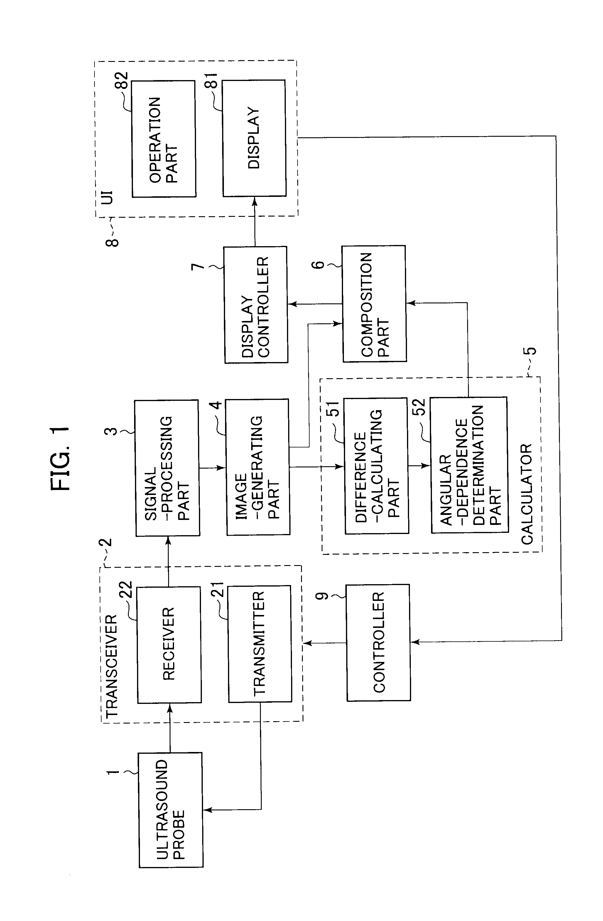
[0014]An ultrasound diagnosis apparatus according to a first embodiment is explained with reference to FIG. 1. FIG. 1 is a block diagram of an ultrasound diagnosis apparatus according to the first embodiment. The ultrasound diagnosis apparatus according to the first embodiment includes an ultrasound probe 1, a transceiver 2, a signal-processing part 3, an image-generating part 4, a calculator 5, a composition part 6, a display controller 7, a user interface (UI) 8, and a controller 9.

Ultrasound Probe 1

[0015]For the ultrasound probe 1, a one-dimensional array probe in which multiple ultrasound transducers are arranged in a single row in the scanning direction may be used, or a two-dimensional array probe in which multiple ultrasound transducers are arranged two-dimensionally may be used. The ultrasound probe 1 transmits ultrasound waves to a subject, and receives reflected waves from the subject as echo signals.

Transceiver 2

[0016]The transceiver 2 includes a transmitter 21 and a rece...

second embodiment

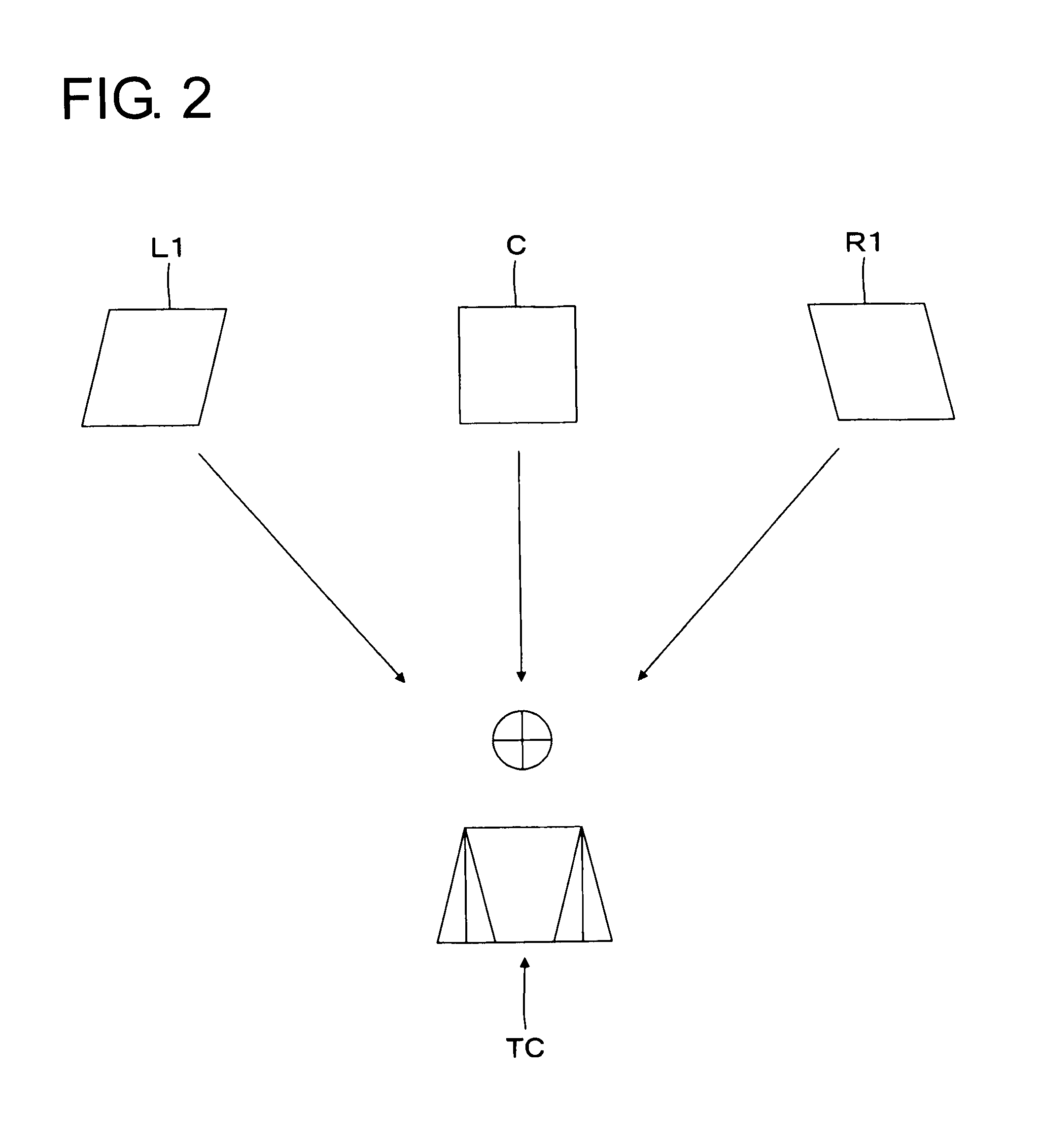
[0095]The following is a description of an ultrasound diagnosis apparatus according to a second embodiment, with reference to FIG. 6. FIG. 6 is a block diagram of an ultrasound diagnosis apparatus according to the second embodiment. The ultrasound diagnosis apparatus according to the second embodiment includes a calculator 5A and a composition part 6A instead of the calculator 5 and the composition part 6 of the first embodiment. Configurations other than the calculator 5A and the composition part 6A are identical to those of the ultrasound diagnosis apparatus according to the first embodiment, and descriptions thereof are therefore omitted. As one example, a case is described in which, as in the first embodiment, ultrasound waves are deflected at a first deflection angle, a second deflection angle, and a third deflection angle, and the tomographic image data C (x, y), the tomographic image data L1 (x, y), and the tomographic image data R1 (x, y) are generated.

Calculator 5A

[0096]Ba...

third embodiment

[0112]The following is a description of an ultrasound diagnosis apparatus according to a third embodiment. As in the first embodiment, the ultrasound diagnosis apparatus according to the third embodiment also obtains the angular dependence pattern ADP (x, y) of multiple images (each pixel in the images) obtained by a compound scan. Moreover, it is also similar in that each image is assigned weights. However, unlike the first embodiment, the third embodiment changes the composition method according to the imaging area or the trend. In other words, in accordance with the part, etc. shown in an image, a setting is made for either a composition method in which the pixels of each weighted image are averaged, or a composition method using the maximum or minimum values of each weighted image.

[0113]For example, for an image showing a part where random noise such as speckles is easily occurred, the implementation of smoothing with the composition method of averaging weighted images is more e...


PUM


Abstract

An ultrasound diagnostic device that is able to generate images with high sensitivity for structures and unnoticeable artifacts. The ultrasound diagnosis apparatus includes an image-capturing part, a calculating part, and a composition part. The image-capturing part deflects ultrasound waves at a plurality of different deflection angles to transmit ultrasound waves to a subject, receives echo signals from the subject, and generates a plurality of ultrasound image data in which the deflection angles of the ultrasound waves are different in each. The calculating part obtains, based on the plurality of ultrasound image data, the trend of the angular dependence of the plurality of ultrasound image data on the deflection angles. The composition part changes the weights of the plurality of ultrasound image data in accordance with the trend of the angular dependence, and composes the plurality of ultrasound image data.

Description

TECHNICAL FIELD[0001]Embodiments described herein relate generally to an ultrasound diagnosis apparatus.BACKGROUND ART[0002]For an ultrasound diagnosis apparatus, there is technology known as compound scanning. In compound scanning, ultrasound waves (transmission beams) are transmitted to a subject by changing the deflection angle. Furthermore, in compound scanning, a plurality of ultrasound image data is generated based on each transmission beam that has a different deflection angle. Furthermore, in compound scanning, these multiple ultrasound image data are composed and displayed. One example of a method of compounding ultrasound image data is averaging. The strength of echo signals received by the ultrasound diagnosis apparatus changes depending on the angle formed by a structure inside an organism and a transmission beam. For example, if the short axis cross-section of a blood vessel is scanned using a linear ultrasound probe, the intima above and below the blood vessel is visua...

Claims


Application Information

Patent Timeline
IPC IPC(8): A61B8/14
CPCA61B8/0891A61B8/145A61B8/483G01S15/8995G01S7/52046
Inventor SUMI, ATSUSHIICHIOKA, KENICHINAKAYA, SHIGEMITSU
Owner KK TOSHIBA
Why Eureka
Try Eureka