System for controlling tissue ablation using temperature sensors

a temperature sensor and tissue technology, applied in the field of tissue ablation, can solve the problems of excessive local heating, unsatisfactory effects of medical procedures, and need too much time, and achieve the effects of effective ablation of abnormal tissue focus, blocking aberrant conduction pattern, and high impedan

Active Publication Date: 2012-06-21
BIOSENSE WEBSTER (ISRAEL) LTD
View PDF38 Cites 81 Cited by
  • Summary
  • Abstract
  • Description
  • Claims
  • Application Information

AI Technical Summary

Benefits of technology

[0008]There are tradeoffs between the desire to create a sufficiently large lesion to effectively ablate an abnormal tissue focus, or block an aberrant conduction pattern, and the undesirable effects of excessive local heating. If the radiofrequency device creates too small a lesion, then the medical procedure could be less effective, or could require too much time. On the other hand, if tissues are heated excessively then there could be local charring effects due to overheating. Such overheated areas can develop high impedance, and may form a functional barrier to the passage of heat. The use of slower heating provides better control of the ablation, but unduly prolongs the procedure.
[0009]The level of ablator power (P) and the tissue temperature (T) are key factors in achieving precise control of the delivery of radiofrequency energy by the catheter electrode. Such control is important in achieving consistent therapeutic results, while avoiding excessive injury to surrounding tissues.

Problems solved by technology

There are tradeoffs between the desire to create a sufficiently large lesion to effectively ablate an abnormal tissue focus, or block an aberrant conduction pattern, and the undesirable effects of excessive local heating.
If the radiofrequency device creates too small a lesion, then the medical procedure could be less effective, or could require too much time.
On the other hand, if tissues are heated excessively then there could be local charring effects due to overheating.
Such overheated areas can develop high impedance, and may form a functional barrier to the passage of heat.
The use of slower heating provides better control of the ablation, but unduly prolongs the procedure.

Method used


Image

  • System for controlling tissue ablation using temperature sensors
  • System for controlling tissue ablation using temperature sensors
  • System for controlling tissue ablation using temperature sensors

Examples


embodiment 1

Alternate Embodiment 1

[0073]Reference is now made to FIG. 3, which is a schematic illustration of the controller 39 for the ablation power generator 25 (FIG. 1), which is constructed and operative in accordance with an alternate embodiment of the invention. In this embodiment the temperature sensors 37 (FIG. 2) may be omitted, which reduces manufacturing costs. Indication of the tissue temperature can be obtained by concurrently performing magnetic resonance imaging (MRI), directed at the target tissue. Dependencies of T1, T2, and proton density on temperature are used to relate change in signal strength to temperature.

[0074]MRI signals from field magnets 53 are acquired by a reconstruction processor 55, which is enhanced by a peak calculation module 57 that is linked to a temperature analyzer 59. The temperature analyzer 59 provides a thermometry signal to the port 47 of the ablation module 45. Thus, the MRI system operates as a temperature sensor for purpose of ablation control. T...

embodiment 2

Alternate Embodiment 2

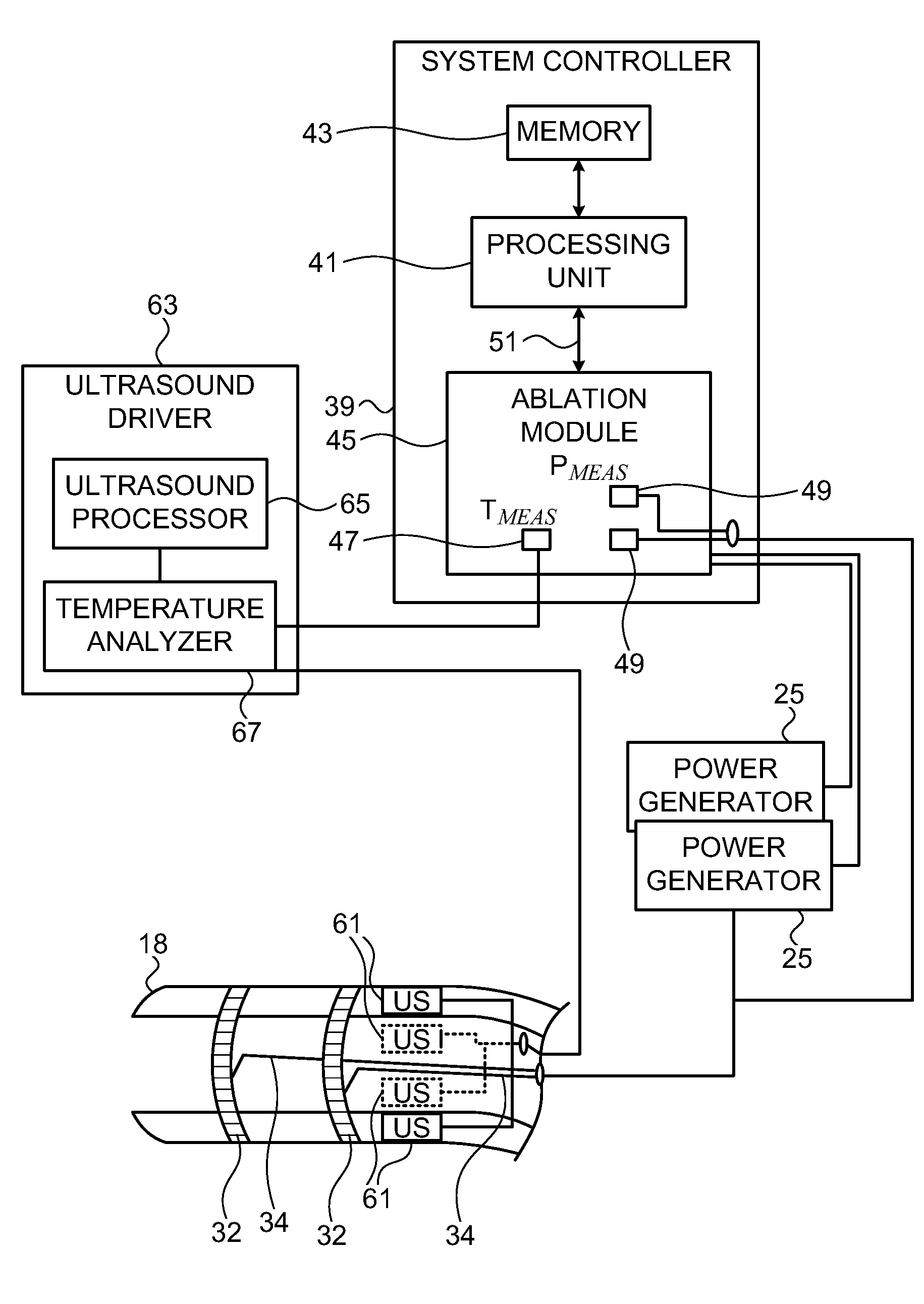
[0075]Reference is now made to FIG. 4, which is a schematic illustration of the controller 39 for the ablation power generator 25 (FIG. 1), which is constructed and operative in accordance with yet another alternate embodiment of the invention. In this embodiment the temperature sensors 37 (FIG. 2) may be omitted. Tissue temperature are measured by assessing thickness of the tissues being ablated, using the teachings described in commonly assigned U.S. application Ser. No. 11 / 357,512, entitled “Lesion Assessment by Pacing”, which is hereby incorporated by reference.

[0076]An array of ultrasound transducers 61 is placed generally near the distal tip 18 of the catheter 14 (FIG. 1), and are energized by an ultrasound driver 63. One example of a suitable ultrasound driver that can be used for this purpose is an AN2300™ ultrasound system produced by Analogic Corporation, Centennial Drive, Peabody, Mass. Ultrasound driver 63 may support different imaging modes such as...

embodiment 3

Alternate Embodiment 3

[0078]The energy sources in the previous embodiments produce RF energy. However, the invention can be carried out using other energy types. For example, in the embodiment of FIG. 4, the electrodes 32 (FIG. 2) can be omitted, and the transducers 61 configured to emit higher levels of ultrasound energy as taught in commonly assigned U.S. Pat. No. 7,156,816, which is herein incorporated by reference.

[0079]Alternatively, the source of ablative energy may be a laser, as disclosed in commonly assigned U.S. Pat. No. 6,997,924, which is herein incorporated by reference.

[0080]In either case temperature may be measured using any of the embodiments disclosed above.


PUM


Abstract

Body tissue ablation is carried out by inserting a probe into a body of a living subject, urging the probe into contact with a tissue in the body, generating energy at a power output level, and transmitting the generated energy into the tissue via the probe. While transmitting the generated energy the ablation is further carried out by determining a measured temperature of the tissue and a measured power level of the transmitted energy, and controlling the power output level responsively to a function of the measured temperature and the measured power level. Related apparatus for carrying out the ablation is also described.

Description

BACKGROUND OF THE INVENTION[0001]1. Field of the Invention[0002]This invention relates to invasive medical devices. More particularly, this invention relates to ablation of tissue using such devices.[0003]2. Description of the Related Art[0004]Ablation of body tissue using electrical energy is known in the art. The ablation is typically performed by applying alternating currents, for example radiofrequency energy, to the electrodes, at a sufficient power to destroy target tissue. Typically, the electrodes are mounted on the distal tip of a catheter, which is inserted into a subject. The distal tip may be tracked in a number of different ways known in the art, for example by measuring magnetic fields generated at the distal tip by coils external to the subject.[0005]A known difficulty in the use of radiofrequency energy for cardiac tissue ablation is controlling local heating of tissue.[0006]Self-regulating tissue ablators have been proposed to achieve the desired control. For exampl...

Claims


Application Information

Patent Timeline
Patent Type & Authority Applications(United States)
IPC IPC(8): A61B18/12A61B17/00A61B18/20A61B18/18A61N7/02
CPCA61B5/01A61B2019/5276A61B18/1206A61B18/1233A61B18/1492A61B18/24A61B2017/00243A61B2018/00023A61B2018/00351A61B2018/00577A61B2018/00648A61B2018/00702A61B2018/00779A61B2018/00791A61N7/022A61B2019/5236A61B5/055A61B2090/374A61B2090/378A61B2017/00092A61B2017/00088A61B2034/2072A61B2034/2053A61B2090/3782A61B18/20A61B18/14A61B18/08
Inventor GOVARI, ASSAFEPHRATH, YARONALTMANN, ANDRES CLAUDIO
Owner BIOSENSE WEBSTER (ISRAEL) LTD
Why Eureka
Try Eureka