
Low level laser therapy for low back pain

a low-level laser and low-level technology, applied in the field of low-level laser therapy for low-level back pain, can solve the problems affecting the subject and the proper functioning, and limiting the flow of nutrients into the disc as well as the flow of waste products out of the disc, so as to achieve the effect of reducing the flexibility of the disc and restoring the flexibility

Inactive Publication Date: 2012-06-21
KYPHON
View PDF6 Cites 38 Cited by
  • Summary
  • Abstract
  • Description
  • Claims
  • Application Information

AI Technical Summary

Benefits of technology

[0006]Degeneration of the ECM (leading to decreased disc flexibility) is believed to benefit from the application of red light irradiation of the disc, which helps the disc regain its flexibility. Since there is evidence for anti-inflammatory effects of LLLT, as well as beneficial effects on fibroblast function and acceleration of connective-tissue repair, the treatment is believed to affect both the nerve endings surrounding the disc as well as the disc itself. In an exemplary embodiment, the red light has a wavelength of between 600 nm and 1000 nm. It is believed that red light having a wavelength of between 600 nm and 1000 nm delivered to the lumbar spine will provide a useful therapy to treat pain and / or degeneration of the disc, for example, in the lower lumbar region.
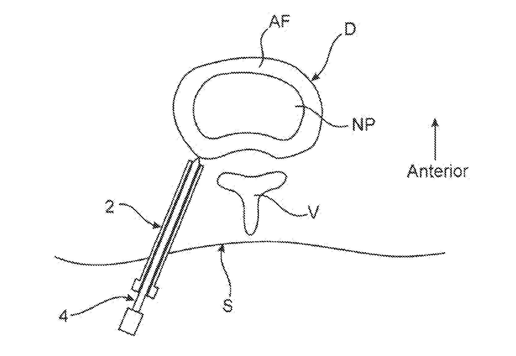
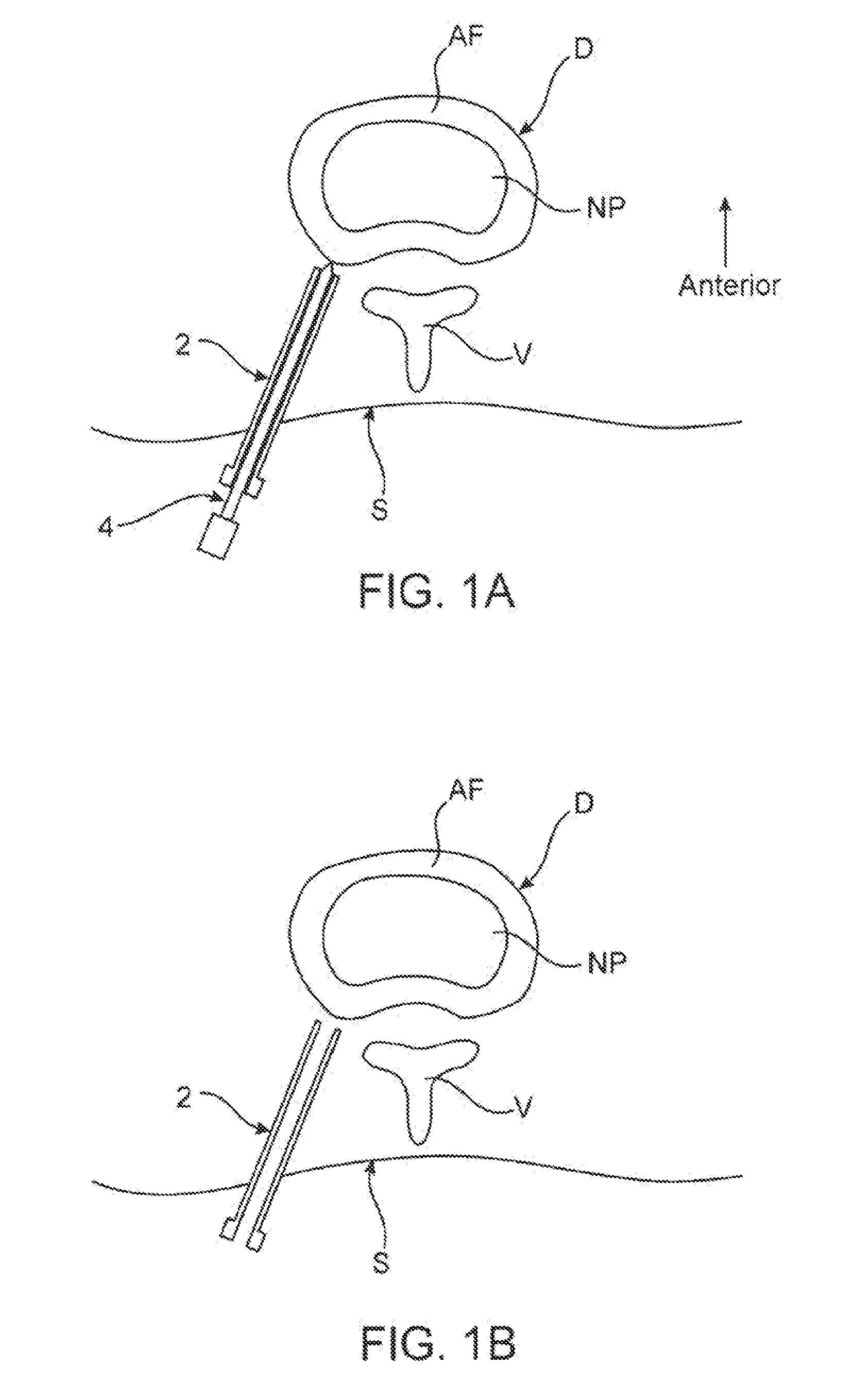
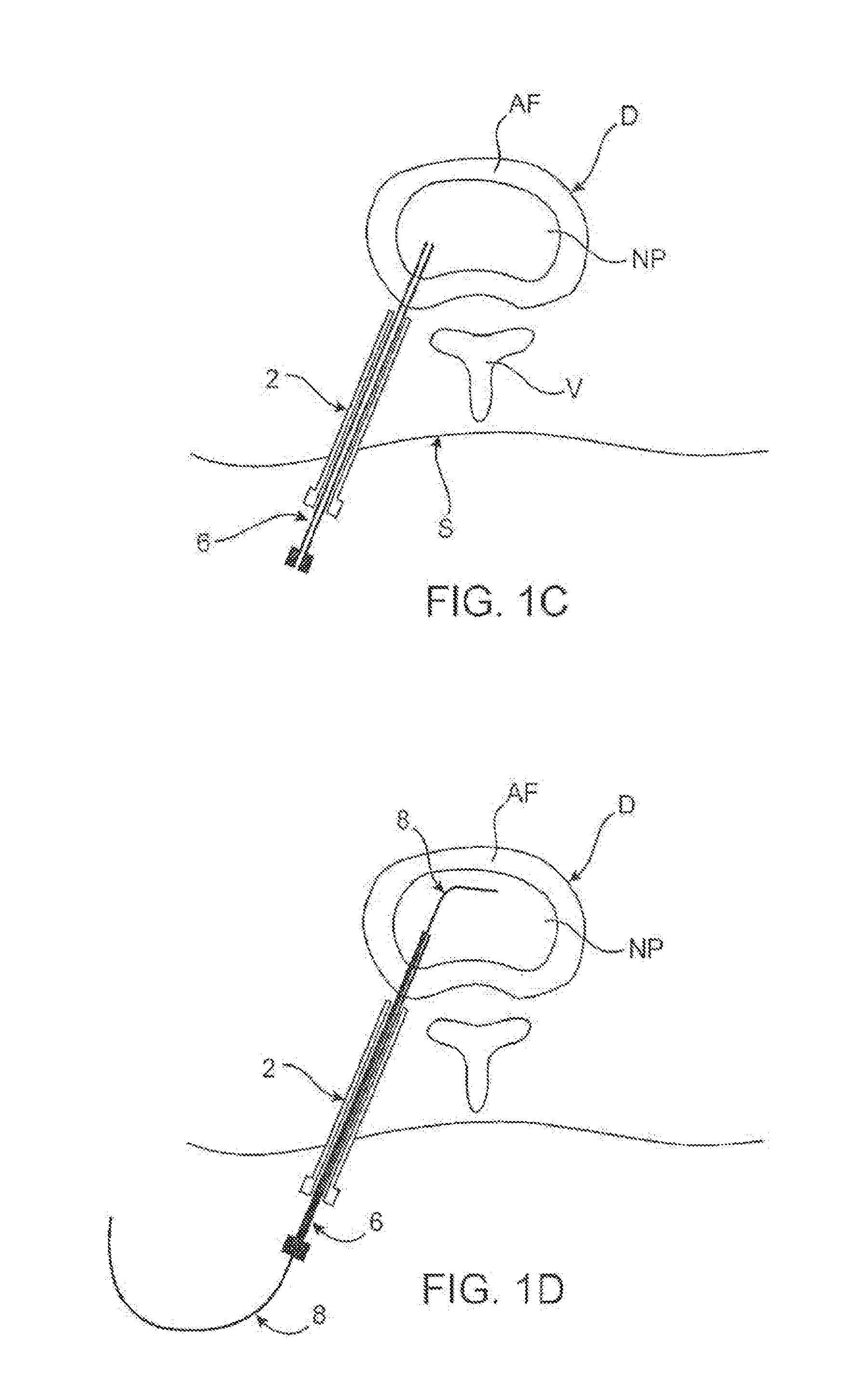
[0016]In another exemplary embodiment, the catheter device may either be advanced to a position within the disc or to a position just outside the disc. In either case, the catheter device may have a distal end or portion configured to facilitate advancement of the distal end through the annulus fibrosis. In some embodiments, the catheter device is passed over a guidewire. In some cases, the catheter is passed over the guidewire within the needle, while in alternative embodiments an introducer is removed over the guidewire before the catheter device is passed over the guidewire. In some embodiments, positioning the distal portion is facilitated by visualizing at least one radiopaque marker or material at or near the distal portion to assess its location.
[0025]Optionally, the catheter body may also include an outer surface having one or more markings for indicating depth of insertion of the catheter device into a patient's body. In other embodiments, the catheter body may include an outer surface having two or more different colors for indicating depth of insertion of the catheter device into a patient's body. The catheter body may further include at least one radiopaque marker or material for facilitating visualization of the catheter device in a patient.
[0026]In an exemplary embodiment, the catheter device includes an injection tube extending through at least part of the lumen of the catheter body for introducing one or more substances into the disc, an inflation tube extending through at least part of the lumen for expanding the deployable anchoring member and a therapeutic energy conduit extending through at least part of the lumen for delivering therapeutic energy to a therapeutic delivery surface. The catheter body, therapeutic energy conduit and / or injection tube may be made of any suitable material or combination of materials, such as but not limited to, stainless steel, tempered stainless steel, annealed stainless steel, polymers, flexible plastics, optical fiber, an electrical wire or conduit, superelastic alloys and / or other suitable materials. In some embodiments, the therapeutic energy conduit, injection tube and / or inflation tube exit a proximal end of the catheter body and are removably coupled with at least one adapter to provide for application of therapeutic energy, injection and inflation. In some embodiments, the therapeutic energy conduit, injection tube and inflation tube extend through at least part of the catheter body lumen coaxially. Alternatively, the therapeutic energy conduit, injection tube and inflation tube may extend through at least part of the catheter body lumen side-by-side. In other embodiments, the therapeutic energy conduit, injection tube and inflation tube may extend through part of the catheter body lumen coaxially and through another part of the lumen side-by-side. In an alternative embodiment, the catheter body comprises the therapeutic energy conduit and may optionally include one or more surface coatings to prevent discharge of the energy in undesired locations along the catheter body. In another embodiment, the catheter comprises a single extrusion having an injection lumen for introducing one or more substances into the disc and an inflation lumen for expanding the at least one anchoring member, with the therapeutic energy conduit located within the lumen, within the catheter body or outside of the catheter body.
[0028]In various embodiments, the catheter device may have any suitable proximal end configurations for providing connection to one or more therapeutic energy sources, injection, inflation, suction, irrigation or other devices, for providing guidewire access and / or the like. In one embodiment, for example, a proximal end of the proximal portion of the catheter body is trifurcated into three separate catheter body proximal ends. In some embodiments, each of the three proximal ends is removably coupled with an adapter for facilitating energy delivery, injection or inflation.

Problems solved by technology

In other instances, the pumping action of the disc may malfunction (due to, for example, a decrease in the proteoglycan concentration within the nucleus pulposus), thereby retarding the flow of nutrients into the disc as well as the flow of waste products out of the disc.
All of these events are detrimental to the subject and the proper functioning of the disc.
However, the lumbar spinal region is located deep beneath the skin, making external treatment largely ineffective.

Method used


Image

  • Low level laser therapy for low back pain
  • Low level laser therapy for low back pain
  • Low level laser therapy for low back pain

Examples


Embodiment Construction

[0041]For the purposes of promoting an understanding of the principles of the invention, reference will now be made to certain embodiments and specific language will be used to describe the same. It will nevertheless be understood that no limitation of the scope of the invention is thereby intended, such alterations and further modifications in the illustrated device, and such further applications of the principles of the invention as described herein being contemplated as would normally occur to one skilled in the art to which the invention relates.

[0042]The uses of the terms “a” and “an” and “the” and similar references in the context of describing the invention (especially in the context of the following claims) are to be construed to cover both the singular and the plural, unless otherwise indicated herein or clearly contradicted by context.

[0043]Recitation of ranges of values herein are merely intended to serve as a shorthand method of referring individually to each separate va...


PUM


Abstract

The invention provides an energy source emitting, such as a low level laser light, catheter having a throughbore, an energy emitting surface disposed near the distal end of the catheter that is connected, directly or indirectly, to the energy source, which allows for the application of therapeutic energy to treat internal areas of a patient that have been accessed by way of a catheter.

Description

BACKGROUND[0001]The present invention relates generally to an instrument to apply low level laser therapy to sites within a subject and methods of using the same.[0002]Any publications or references discussed herein are presented to describe the background of the invention and to provide additional detail regarding its practice. Nothing herein is to be construed as an admission that the inventors are not entitled to antedate such disclosure by virtue of prior invention.[0003]The intervertebral disc contains a nucleus pulposus surrounded by an annulus fibrosus. The nucleus pulposus provides the primary shock absorbing characteristics and the laminated nature of the annulus fibrosus provides the bulk of the tensile strength.[0004]In a healthy intervertebral disc, cells within the nucleus pulposus produce an extracellular matrix (ECM) containing a high percentage of proteoglycans. These proteoglycans retain water, which provides at least some of the shock absorbing characteristics of t...

Claims


Application Information

Patent Timeline
IPC IPC(8): A61N5/06
CPCA61N2005/0612A61N5/0601
Inventor LEE, ELAINE
Owner KYPHON
Learn More