Method of determining reservoir pressure

a reservoir pressure and reservoir technology, applied in the field of hydrocarbon exploration and production, can solve the problems of limited injection rate/volume, careful measurement of pumping volumes, etc., and achieve the effect of low permeability

Active Publication Date: 2012-06-21
BP CORP NORTH AMERICA INC
View PDF2 Cites 48 Cited by
  • Summary
  • Abstract
  • Description
  • Claims
  • Application Information

AI Technical Summary

Benefits of technology

[0008]These and other needs in the art are addressed in one embodiment by a method of determining reservoir pressure in a gas well. Embodiments of the method have application in different type of gas reservoirs, but are primarily targeted for use in tight gas and shale reservoirs (e.g. low permeability gas reservoir systems). It is however recognized that the method also may be used in conventional reservoirs (both gas and oil), tight oil, shale oil and coalbed methane reservoirs. In an embodiment, the method initially includes performing a series of injection events with discrete stages, determining the

Problems solved by technology

A small amount of fluid may injected to ensure perforations are open, but careful measurement of volumes pumped a

Method used


Image

  • Method of determining reservoir pressure
  • Method of determining reservoir pressure
  • Method of determining reservoir pressure

Examples


Embodiment Construction

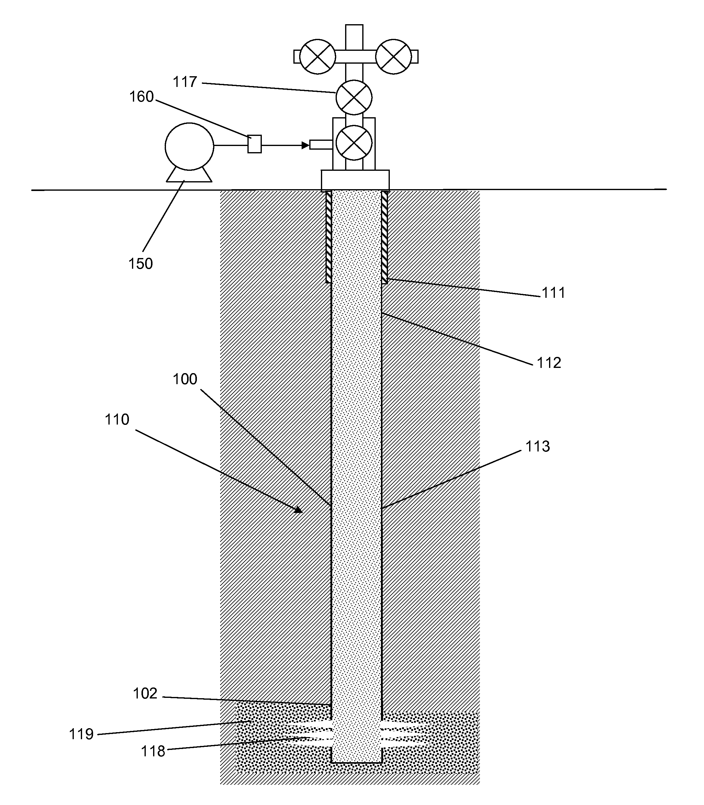
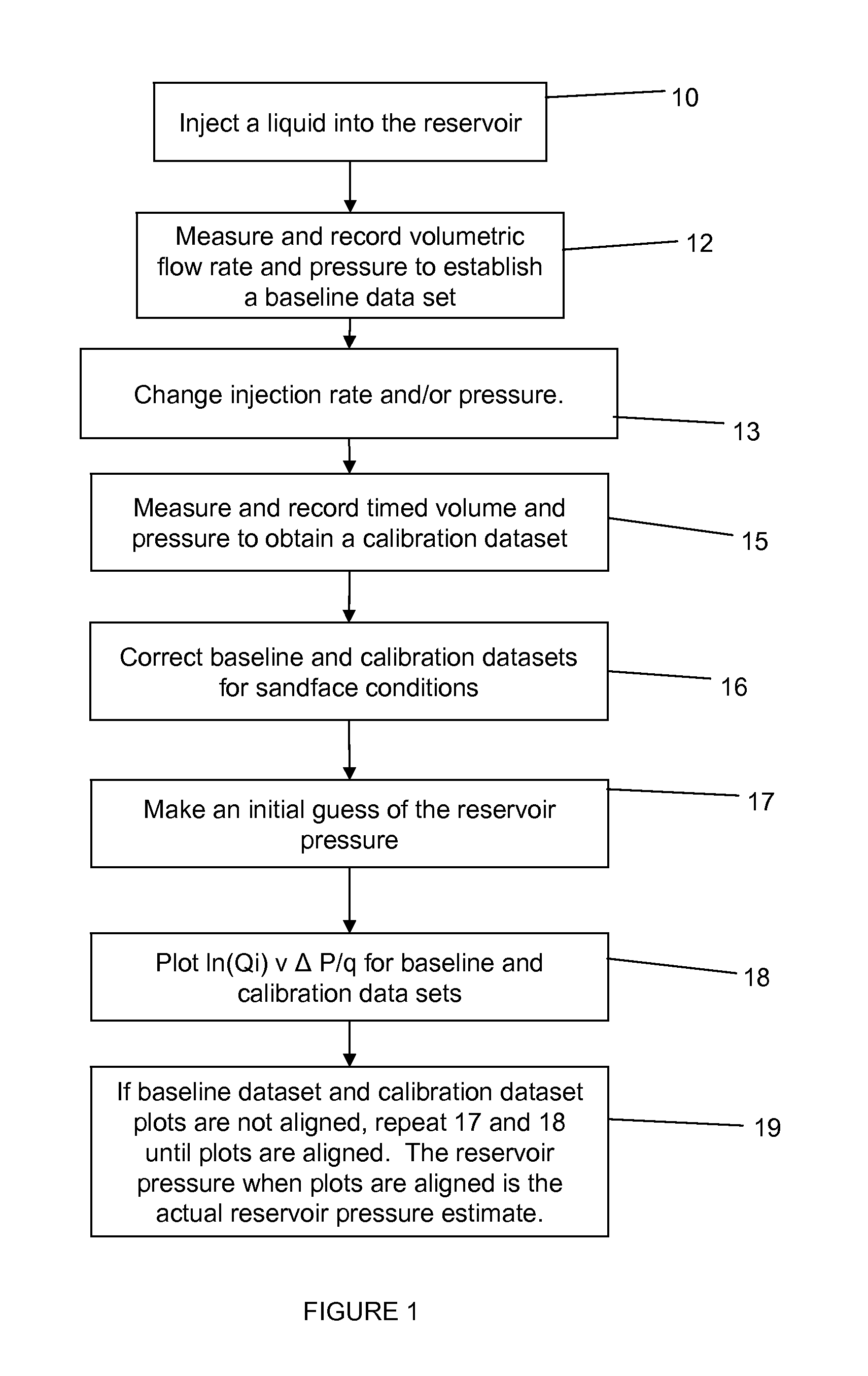
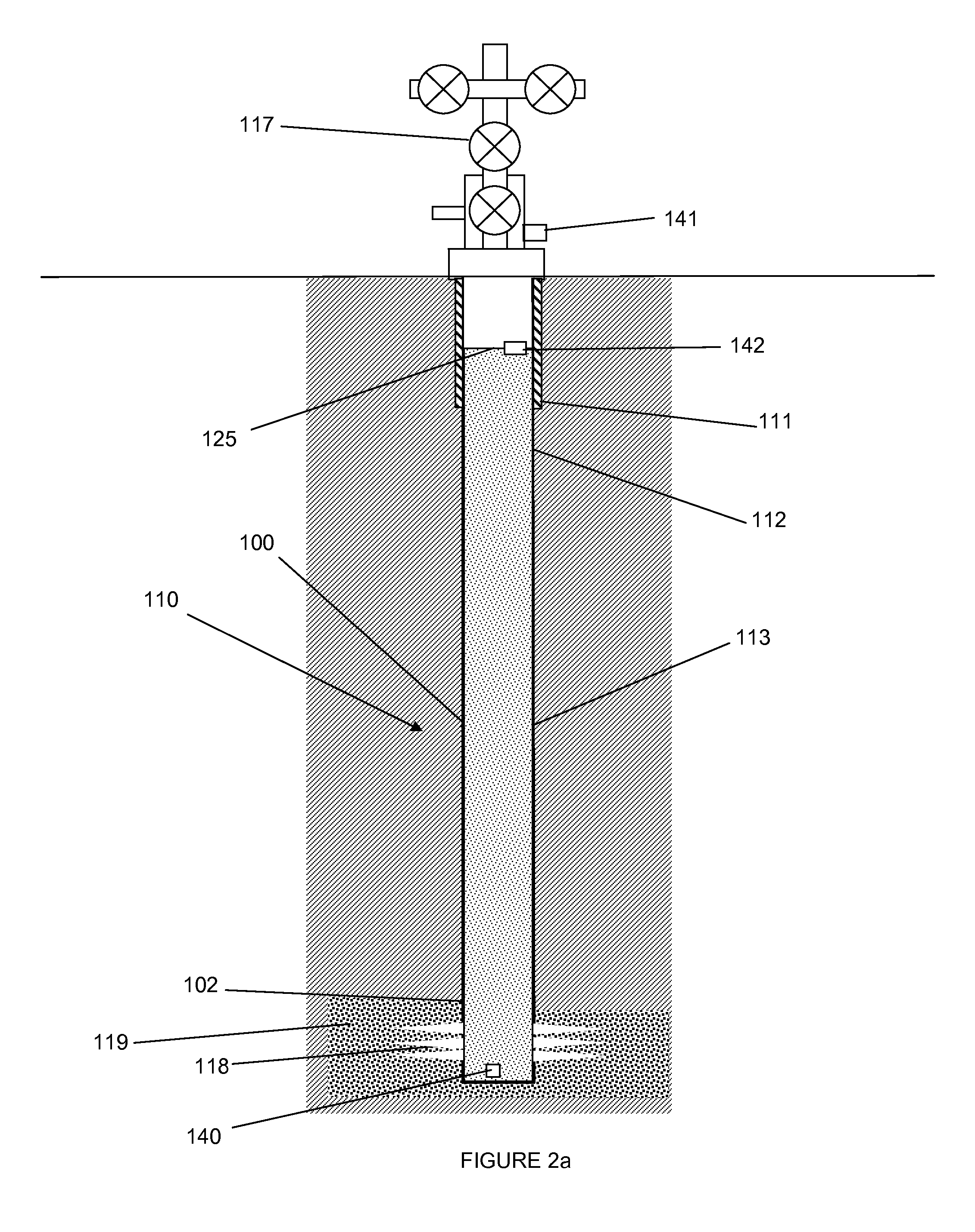
[0030]FIG. 1 is a flowchart depicting an embodiment of a method for determining reservoir pressure. In an embodiment, the method preferably is applied to wells with a new isolated set of perforations 118 in a well has not begun hydrocarbon production. More particularly, fluid may be injected into the well and into the formation 119 in block 10, preferably prior to fracturing or other injection of material into the reservoir. However, it is envisioned that fluid may be injected at any time during the completion or production process into the reservoir. In one embodiment, the fluid injection rate may be limited to injection rates / volumes which minimize the creation of any hydraulic fracture length during the test. The fluid may be any suitable fluid such as without limitation, saline fluid, water, potassium chloride fluid, ionic fluid, non-ionic fluid, or combinations thereof. Gaseous fluids could also be used. All embodiments of the method include injection stages generated by discre...


PUM


Abstract

A new approach is disclosed for measuring the pressure of tight gas reservoirs, using information obtain from continuous injection prior to hydraulic fracture stimulation. The technique can be obtained utilizing either bottom-hole or surface pressure gauges and properly instrumented surface injection pumps. The analysis is completed by plotting injection and rate data in a specialized form from terms arranged in Darcy's radial flow equation to obtain a curve or trend. The key component to proper application of this technique is to obtain both baseline and one or more calibration data sets. These calibration data sets are obtained by either increasing or decreasing the injection pressure and/or rate from the baseline data. Initial reservoir pressure is assumed, but the calibration data indicates if the guess was too high or low. Accurate estimates of reservoir pressure may be obtained in a few iterations.

Description

CROSS-REFERENCE TO RELATED APPLICATIONS[0001]This application claims the benefit of U.S. Provisional Application Ser. No. 61 / 423,692, filed Dec. 16, 2010, and is incorporated herein by reference in its entirety for all purposes.STATEMENT REGARDING FEDERALLY SPONSORED RESEARCH OR DEVELOPMENT[0002]Not applicable.BACKGROUND[0003]1. Field of the Invention[0004]This invention relates generally to the field of exploration and production of hydrocarbons. More specifically, the invention relates to a method of determining reservoir pressure in hydrocarbon reservoirs.[0005]2. Background of the Invention[0006]Increasingly, hydrocarbon resource is being developed in low permeability reservoirs. For example, more than 50%) of the currently identified gas resources in the United States is found within tight gas and shale gas reservoirs (ref. Table 9.2 of the US EIA report titled “Assumptions to Annual Energy Outlook 2011” http: / / 38.96.246.204 / forecasts / aeo / assumptions / pdf / 0554(2011).pdf). Estima...

Claims


Application Information

Patent Timeline
IPC IPC(8): G06F19/00G01V9/02
CPCE21B49/008E21B47/06E21B49/003E21B49/0875G01V9/02
Inventor ADAMS, JOHN R.MOTEALLEH, SIYAVASHSEBASTIAN, HERBERT M.JIANG, YUANLINDOTSON, BRYAN
Owner BP CORP NORTH AMERICA INC
Why Eureka
Try Eureka