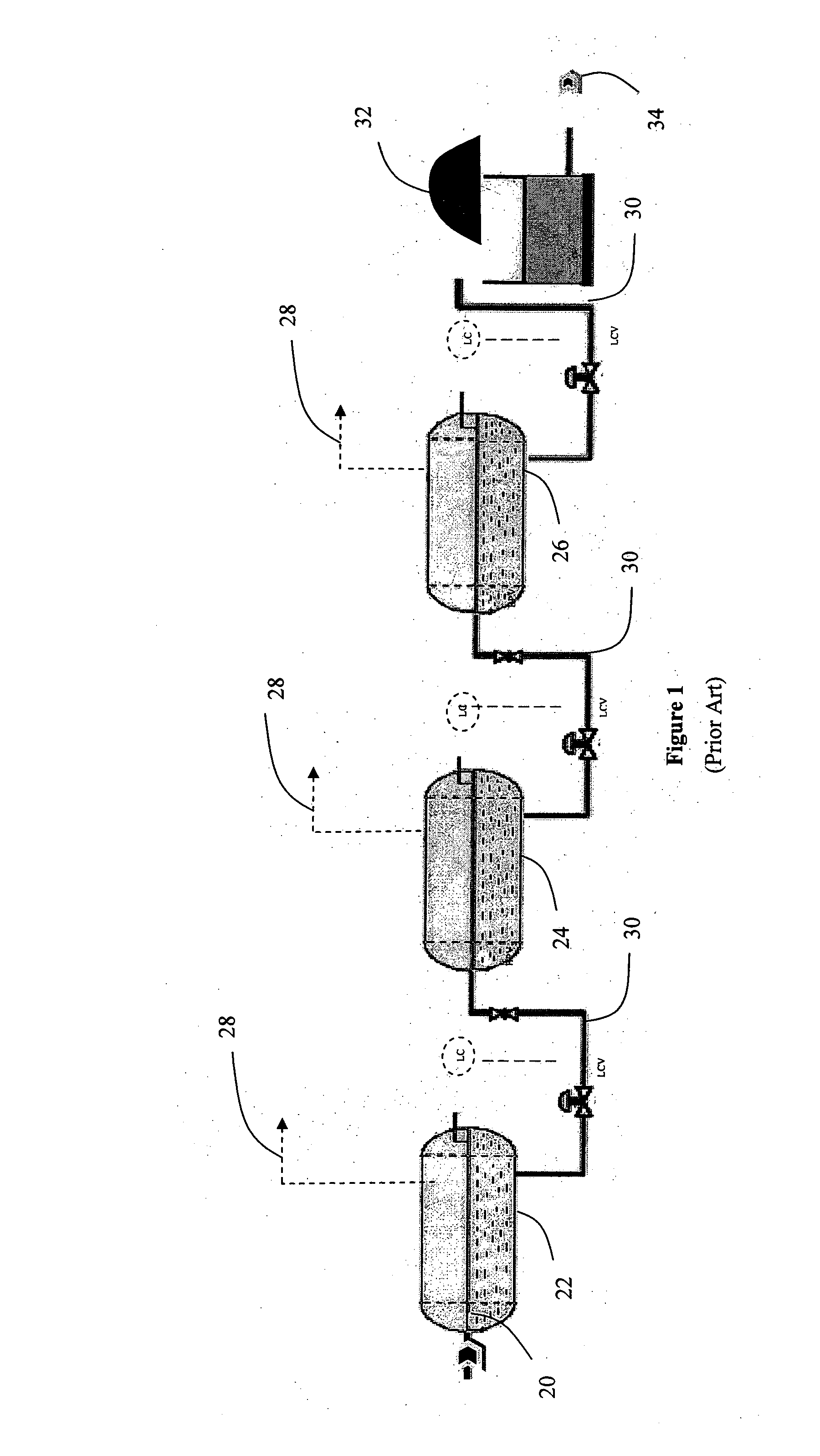
This conventional means of separating oil, gas and water and stabilizing the oil however is very energy intensive mainly due to inlet gas, oil and
water heating requirements that result in
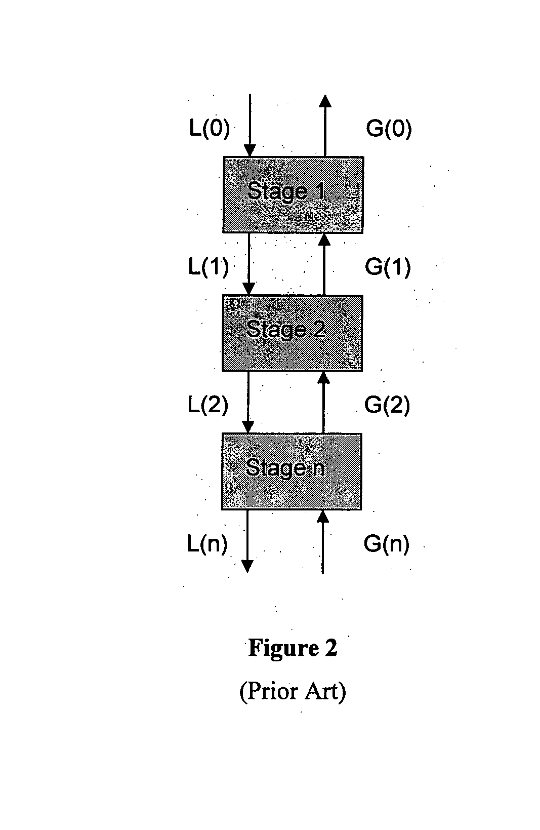
high energy consumption, Also, a multistage
separation system, typically with 2 or 3 separation stages, results in low
recovery of valuable stabilized liquids as such a
separation system in inherently relatively inefficient in terms of stabilized
liquid product recovery.
It must also be added that such conventional separation systems are bulky and not particularly economical.
However, conventional stabilizer columns are tall and are typically not utilized offshore particularly on floating facilities as the motion effects are significantly amplified with tall columns thus impacting their performance.
This is a problem particularly for offshore facilities where turndown of as low as 10% of design rate is required.
An additional drawback of the
system is that the design liquid flow rates are generally high, resulting in a large column liquid boot section.
This results in excessive heat duty being required at the
reboiler.
High heat duty requirements can significantly increase the complexity of the heating medium supply system apart from reducing the energy efficiency of the facility.
The columns will generally require more
downtime for maintenance and are more prone to failure compared to separators.
Another problem besetting conventional crude oil separating systems is that of slugging.
Crude oil production receiving facilities particularly those receiving production from multi-phase
subsea pipelines are susceptible to slugs arriving from multiphase pipelines and risers.
Slugs generated in the pipelines and risers not only require
processing facilities to be increased in size to accommodate the slugs, but also results in production upsets associated with the high speed at which the slugs arrive and the transient pressure fluctuations due to the surge of gas following the arrival of the slugs.
Under these scenarios the production facilities like inlet heat exchangers, production separators and downstream gas compressors generally will not be able to cope with this transient slugging phenomenon resulting in production upsets and possibly shutdown.
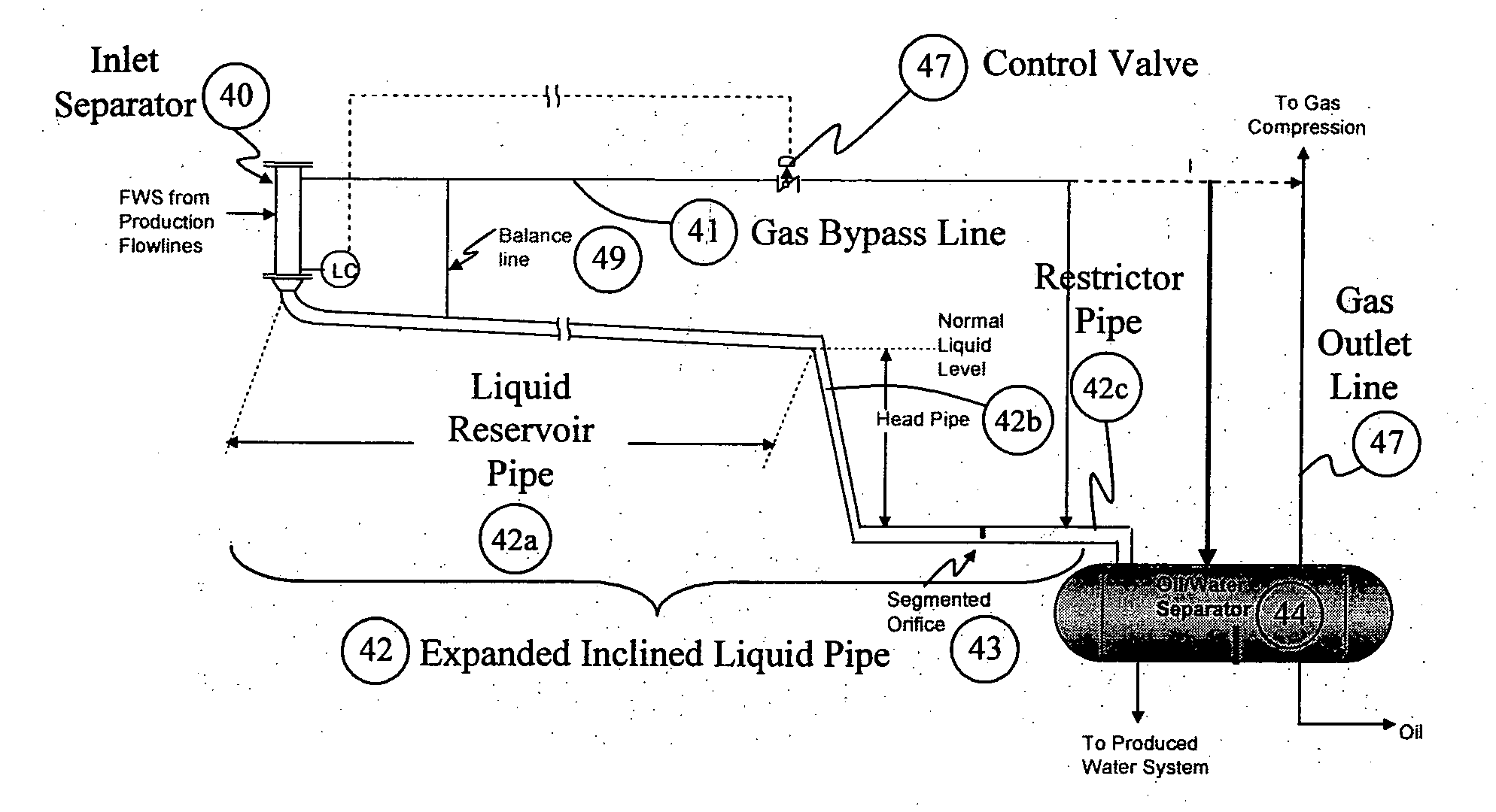
While serving its purpose of dampening slugs well, this ChevronTexaco
slug damper suffers from a drawback in that as the liquid reservoir 4 has a constant inclination, it will have only limited
slug handling capacity.
Thus at
design flow, the liquid reservoir 4 will generally be full of liquid and will not have further slug handling capacity, resulting in unfavorable
backup of liquid into the gas bypass 3 line.
In addition, this ChevronTexaco slug
damper does not provide any means for managing the slugs in the liquid reservoir 4 as the speed with which the liquids flow through the orifice depends solely on the available liquid static head.
Whilst this ChevronTexaco slug
damper is suitable for the specific application with a compact cyclonic separator (GLCC), it is not suitable for general applications where slug handling and stable flow to the downstream system are required.
Conventional slug catchers, if adequately sized, will be able to accommodate the slugs and control liquid flow to the downstream system, but this will result in
large vessel sizes with
control valves at both the gas and liquid outlet lines and possibly at the inlet.
These, in many cases, are expensive with low reliability (due to the controls at the outlet lines and possibly at the inlet line) and are generally too large for installation on offshore facilities.
An additional problem with these conventional slug catchers is that they do not suppress the typically large gas surge that follows a liquid slug.
After the slug arrives at the outlet of the pipeline or production platform, the compressed gas creates a large gas surge, which again may result in major upsets in topside facilities, like the downstream gas compression trains.
However, without effective separation upstream, heating duties will be high as both the gas
stream and liquid streams are heated and this will also increase cooling duty requirements as the gas will need to be cooled prior to compression.
In addition, without effective slug suppression upstream, the performance of the
heat exchanger will not be good due to slug flow conditions at the exchanger.
In addition, the presence of sand in the production fluid often results in sand build-up in the downstream separator which in turn possibly requires frequent shutdowns to remove sand from the separator or requires sand removal devices to be installed at the separator which are expensive.

