Device And Method For Particle Beam Production

a particle beam and accelerator technology, applied in the field of pulse beam accelerators, can solve the problems of inability to use synchrocyclotrons in combination with synchrocyclotrons, limited synchrocyclotrons in current proton therapy facilities, and difficult to use beam time structures in combination with spot scanning techniques

Active Publication Date: 2012-06-28
ION BEAM APPL
View PDF3 Cites 25 Cited by
  • Summary
  • Abstract
  • Description
  • Claims
  • Application Information

AI Technical Summary

Problems solved by technology

In order to accommodate to the specific time structure of the synchrocyclotron beam, all current proton therapy facilities having a synchrocyclotron are limited to the use of the so-called double scattering technique for delivering charged particle radiation therapy.
More advanced techniques for delivering charged particle radiation therapy such as the so-called scanning technique have not been used in combination with a synchrocyclotron due to problems resulting from the specific time structure of the extracted beam.
One of the problems with a pulsed accelerator is that it is difficult to use such a beam time structure in combination with a spot scanning technique.
Knowing that a typical target volume is divided in about 5000 to 10000 voxels, the total irradiation time of the target volume is of the order of 1000 to 2000 seconds, which is an unacceptable long irradiation time.
For other types of accelerators producing a pulsed beam, the same problem as described above will be encountered.
However, this method can not be applied to regulate the intensity of a single beam pulse extracted from a synchrocyclotron having the time structure as described above.
Indeed, at the time the intensity of the beam pulse extracted from the synchrocyclotron is measured, the ion source is already shut off since a long time.
Hence, it is impossible to use the measured intensity or number of particles within an extracted beam pulse and correct a control parameter of the ion source (or any other device that can vary the beam pulse intensity) to adjust the intensity of this same beam pulse that is already extracted from the accelerator.
Accordingly, no practical solution has been proposed so far to regulate the extracted beam from a pulsed accelerator on a pulse per pulse basis which may solve the above-mentioned drawbacks.

Method used


Image

  • Device And Method For Particle Beam Production
  • Device And Method For Particle Beam Production
  • Device And Method For Particle Beam Production

Examples


Embodiment Construction

[0067]The present invention will be now described in detail in relation to the appended drawings. However, it is evident that a person skilled in the art may conceive several equivalent embodiments or other ways of executing the present invention. The spirit and the scope of the present invention are therefore limited only by the terms of the claims.

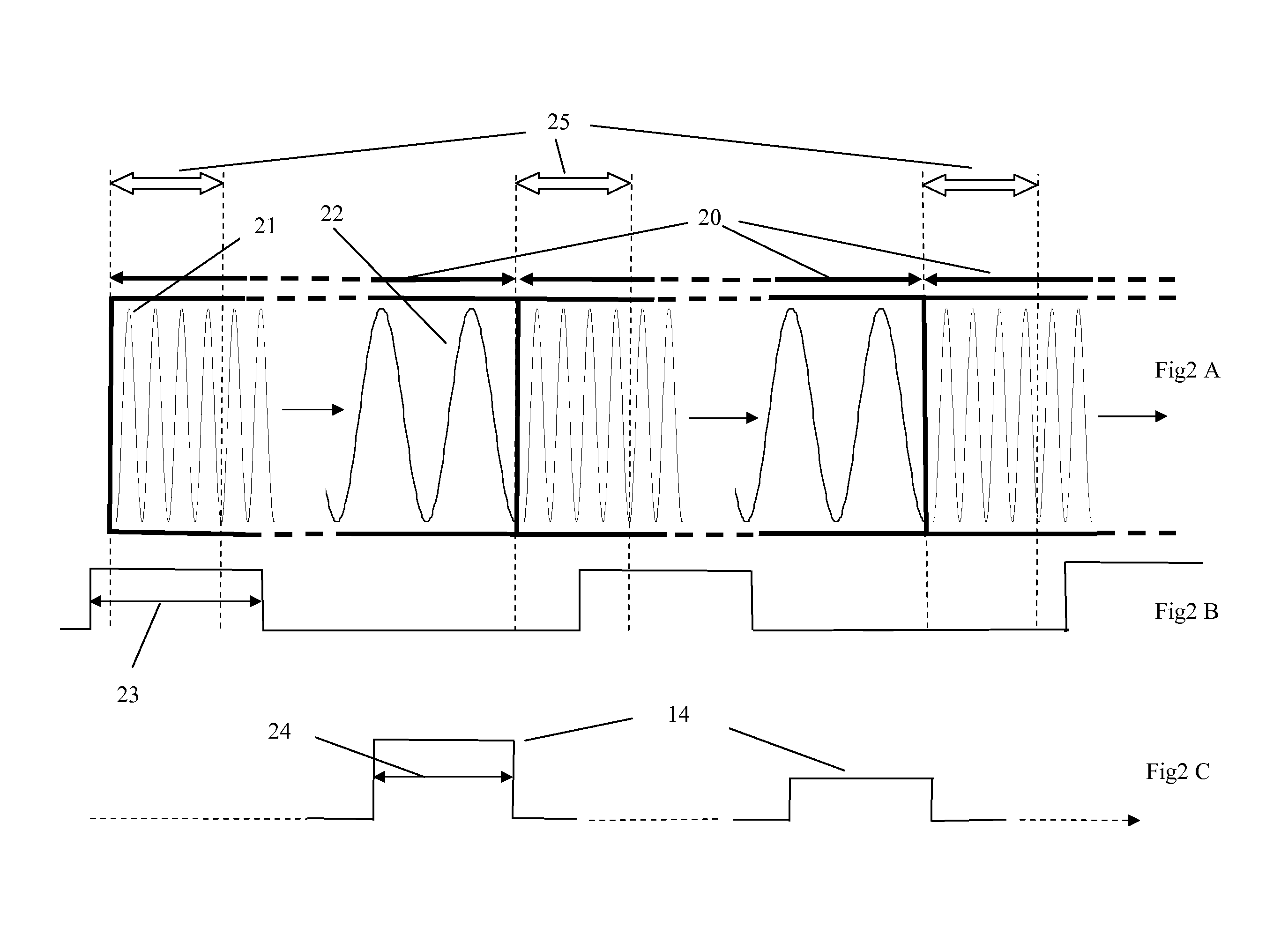
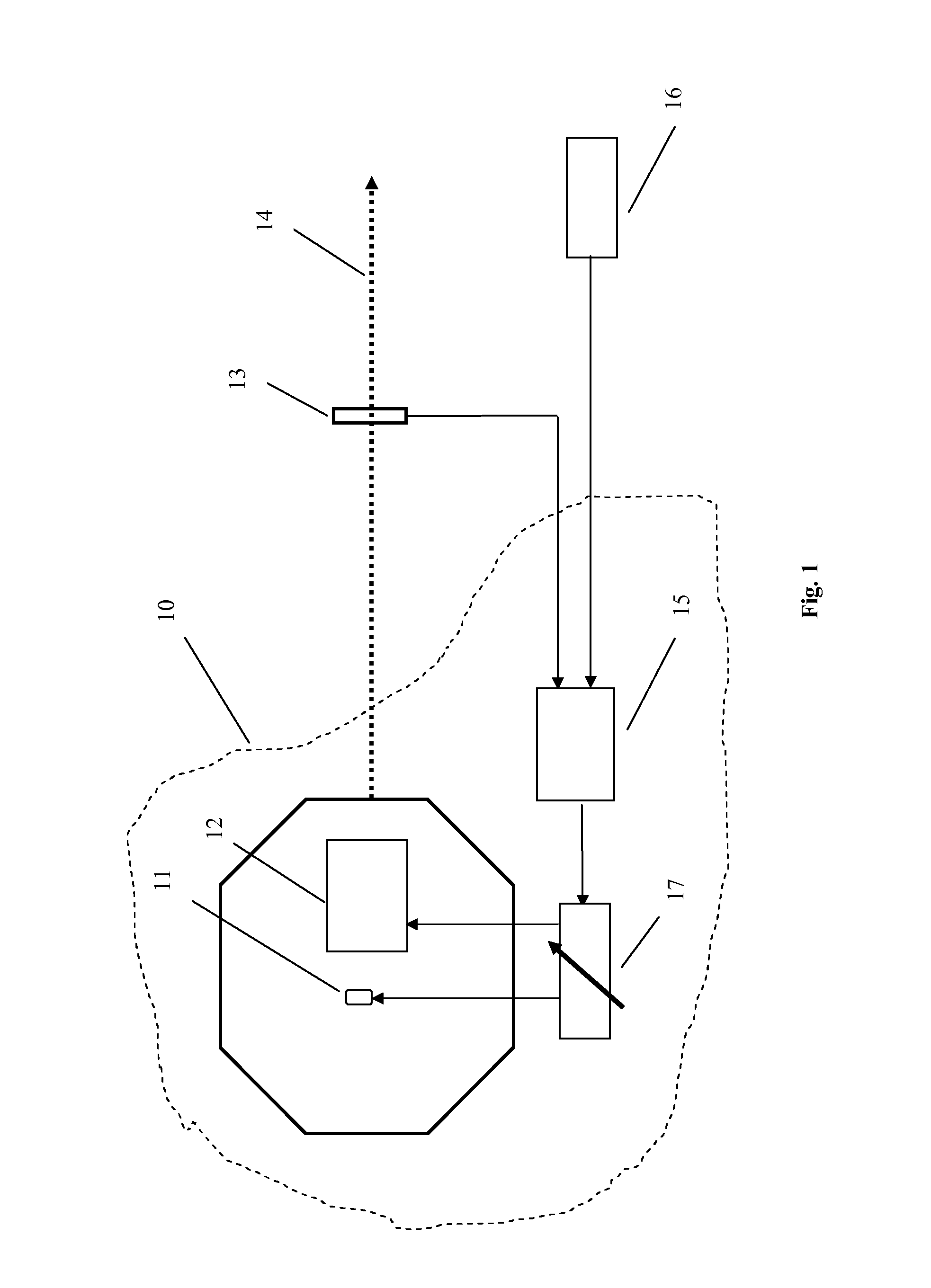
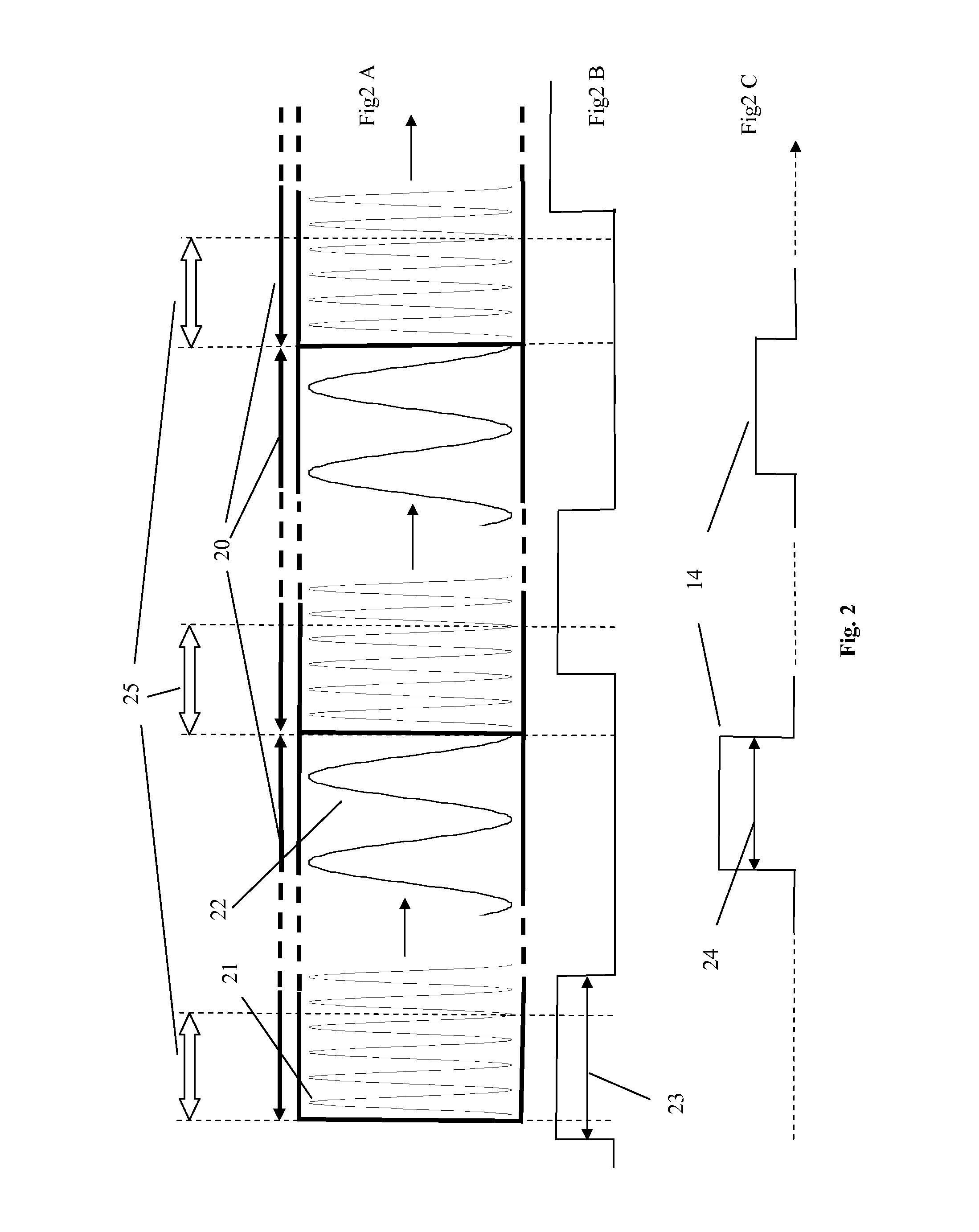
[0068]FIG. 1 shows a schematic representation of a particle accelerator 10 and its controls according to the invention and some additional elements. The particle accelerator 10 (e.g. synchrocyclotron, linear accelerator, fixed field alternating gradient accelerator, . . . ) comprises an ion source 11, a radio frequency (RF) acceleration system 12 and means for varying 17 the number of particles within a beam pulse. Taking the example of a 250 MeV proton synchrocyclotron, typical RF acceleration frequencies are ranging between 50 and 100 MHz. In a synchrocyclotron, the RF acceleration system produces an RF wave with a time varying frequen...


PUM


Abstract

The present invention relates to a pulsed beam particle accelerator which can be used for particle radiation therapy. More particular, a device and method are provided to control the number of particles within a beam pulse. The particle accelerator comprises means for varying the number of particles within each beam pulse of said pulsed ion beam from a minimum value to a maximum value as function of the value of a beam control parameter. For each particle irradiation the required number of particles for each beam pulse is controlled by defining a value for said beam control parameter based on calibration data.

Description

FIELD OF THE INVENTION[0001]The present invention relates to the field of pulsed beam accelerators for use in charged particle radiation therapy (e.g. proton, carbon ion). More particularly, this invention relates to the control of the amount of particles within the beam pulses extracted from the accelerator.STATE OF THE ART[0002]In order to accelerate charged particles to energies for use in charged particle radiation therapy (e.g. up to 250 MeV for proton therapy) many types of accelerators have been developed or proposed. Depending on the specific design of these accelerators some accelerators are producing a continuous particle beam (e.g. isochronous cyclotron) whereas other types of accelerators are producing a particle beam having a pulsed time structure (e.g. synchrocyclotron, fixed field alternating gradient accelerator, linear accelerator). Some basic components that these accelerators have in common is an ion source for producing the ionized particles to be accelerated and...

Claims


Application Information

Patent Timeline
Patent Type & Authority Applications(United States)
IPC IPC(8): A61N5/10H05H7/08
CPCA61N5/1048H05H7/00A61N2005/1087A61N5/1067A61N5/10H05H7/12H05H13/02
Inventor JONGEN, YVES
Owner ION BEAM APPL
Why Eureka
Try Eureka